Test Coax with a Multimeter: Practical Guide
Learn how to safely test coax cables with a multimeter, covering continuity checks, insulation integrity, and practical troubleshooting for DIY electronics and automotive tasks.

Learn how to confirm coax health using a multimeter: check continuity along the center conductor, verify insulation between center and shield, and identify shorts or opens. This quick guide covers essential steps, safety tips, and practical readings for common coax types.
Why testing coax with a multimeter matters
In radio frequency systems, video, data, or control signals ride over coax cables. Testing coax with a multimeter helps you verify basic integrity before committing to more advanced RF tests. By confirming continuity along the center conductor, ensuring the shield is not shorted to the core, and checking insulation between conductors, you reduce the risk of intermittent faults and RF losses. According to 10ohmeter, mastering coax testing with a multimeter is an essential skill for DIY electronics and automotive work, saving time and preventing costly rework. This kind of practical check is particularly valuable for reterminated cables, after field repairs, or before integrating coax into a new prototype. As you read further, you’ll learn safe, repeatable methods you can perform with common tools.
Basic electrical concepts behind coax testing
Coaxial cable consists of a center conductor, an insulating dielectric, a braided shield, and an outer jacket. When you test coax with a multimeter, you’re primarily assessing two things: (1) continuity along the individual conductors (center and shield), and (2) insulation between conductors to ensure there is no unintended short. The multimeter measures resistance, which is inverse to current flow. A healthy coax length will show a predictable resistance on the center conductor and an open (very high) resistance between center and shield. Any unexpected low resistance between center and shield indicates a short or breached insulation. The goal is to confirm that the two conductors stay separate and intact along the tested length.
Safety reminders and lab setup
Always power down connected equipment and disconnect the coax from devices before testing. Work on a non-conductive mat or bench, and keep metal tools away from exposed connector contacts. If you must test near powered circuits, use appropriate isolation and low-energy procedures to avoid shocks or shorts. Wear eye protection when cutting or stripping coax, and keep your work area dry. A quiet, well-lit workspace helps you spot micro-cracks or pinhole leaks that a hurried test might miss. Remember: coax testing is a preliminary check, not a complete RF integrity test.
Essential tools and connectors you’ll use
Before you begin, assemble a basic kit tailored for coax testing with a multimeter:
- Digital multimeter (prefer auto-ranging) with continuity and resistance testing
- Test leads with alligator clips or banana plugs
- Pin probes or miniature grabbers for reaching into connectors
- Adapter tips for common connectors (BNC, SMA, F-type) as needed
- Cable cutters/strippers for clean ends and re-termination
- Optional: a length of spare coax for test leads to avoid damaging the cable under test Using these tools, you’ll be able to perform reliable coax tests without guessing, and you’ll reduce the chance of introducing new faults during probing.
How to prepare your coax for testing
Preparation sets the stage for reliable readings. Inspect the end connectors for corrosion or bent pins. If possible, clean the connector surfaces with a lint-free cloth. Trim the cable ends squarely to expose fresh metal on both the center conductor and the shield. Use the proper adapter so the meter probes connect firmly without slipping. If you’re working with multiple coax types, have a few common adapter tips on hand. Keeping connectors clean and ends square minimizes false readings and makes the test results more trustworthy.
Getting reliable readings: measurement strategies
To test coax with a multimeter, switch the meter to the appropriate mode—continuity or resistance—depending on what you’re testing. For end-to-end checks, test between the center conductor and its own end, then test the shield to shield. You should see the center conductor’s resistance reflect the length and gauge of the wire, while the shield-to-center should show very high resistance (no short). For insulation checks, measure between center and shield with the ends exposed; readings should approach infinity (open circuit) if insulation is intact. If your meter supports capacitance, you can test coax capacitance per meter, but remember that many basic meters cannot rely on that value alone. When you test coax with a multimeter, be sure to document any unexpected readings and re-test to confirm.
Interpreting readings: passing vs failing
A “pass” in this context means the center conductor shows a continuous path along the tested length (low resistance proportional to length) and the center-to-shield path shows high resistance (no short). If you observe near-zero resistance between center and shield, that’s a red flag for a short or breached insulation. Very high resistance but with a broken center path indicates an open circuit. In long cables, you’ll expect higher resistance for the center conductor; repeated measurements at multiple points along the length help localize a fault. If readings drift with slight changes in temperature or handling, retest after giving the system a moment to stabilize.
Real-world test scenarios and troubleshooting
Coax is often used in automotive diagnostics and home electronics projects. When test results reveal a short or open, first inspect connectors for damage, then check the cable’s length and routing for pinch points. A damaged shield frequently occurs near connector bodies where the braid is stressed. If you cannot locate the fault at the connectors, test a known-good section of coax to isolate whether the issue is the length of cable or the connectors. A non-contact RF detector or a dedicated coax tester may be needed for more advanced diagnostics, but for many common faults a basic multimeter provides a quick and repeatable check.
Maintenance, storage, and reusing coax after tests
After testing, store coax properly to prevent kinks or crushing the conductor. Coil loose loops and secure with ties, avoiding tight bends, which can damage the dielectric. If you reterminate ends, use proper stripping techniques and verify there are no stray strands that could cause shorts. Label cables that have shown faults so they don’t get reused in critical RF paths without rework. Regular testing of service cables, especially in automotive or remote installations, helps you head off reliability problems before they escalate.
Tools & Materials
- Digital multimeter(Auto-ranging preferred; set to ohms or continuity)
- Test leads with alligator clips or banana plugs(Shrouded connectors recommended)
- Pin probes or mini grabbers(For reaching into tight coax connectors)
- Connector adapters (BNC, SMA, F-type as needed)(Match the coax type under test)
- Cable cutters/strippers(Helpful for clean ends)
- Spare coax length (test lead)(Use as a non-destructive test lead)
- Non-conductive workspace mat(Improves safety and visibility)
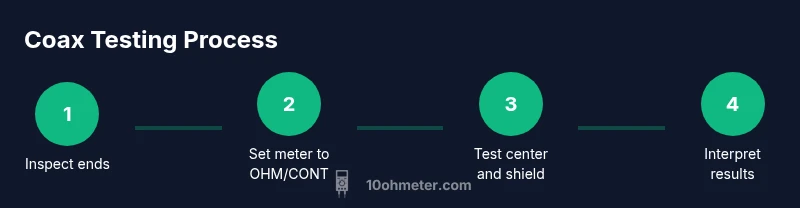
Steps
Estimated time: 25-40 minutes
- 1
Prepare the test setup
Power off all equipment and gather the tools. Inspect the coax ends for damage, choose the right adapters, and clean the connector surfaces. This ensures you’re not reading corrosion or dirt as a fault.
Tip: Pro tip: use a spare coax length as a test lead to avoid touching the live ends. - 2
Inspect the cable visually
Look for cuts, kinks, or crushed jackets. Damaged jackets can expose conductors and compromise readings. If you see damage, don’t reuse the cable until it’s repaired or replaced.
Tip: Pro tip: under magnification, small hairline cracks reveal where insulation has degraded. - 3
Set your meter for continuity and resistance
Configure the meter to continuity (beep) or resistance (ohms). Zero any offset if your meter has a calibration step. Attach leads firmly to the test ends to avoid loose readings.
Tip: Pro tip: clamp the leads to avoid wrist movement that can introduce measurement noise. - 4
Test end-to-end center conductor
Probe the center conductor at one end and the center at the other end. You should see a low resistance proportional to cable length. If the reading is infinite, the center conductors are open.
Tip: Pro tip: if you have multiple sections, test each segment to localize a fault. - 5
Test center-to-shield insulation
Place one probe on the center conductor and the other on the shield at the same end. Expect a very high resistance indicating good insulation. A measurable low resistance indicates a leakage path or shorts.
Tip: Pro tip: perform this test at both ends to confirm consistent insulation integrity. - 6
Document readings and decide on repair
Record the readings and locations of any anomalies. If faults are found, reterminate or replace the affected coax segment. If readings are clean, label the cable as healthy for RF use.
Tip: Pro tip: create a simple checklist for future tests to save time.
Your Questions Answered
Can I test coax with a multimeter for continuity?
Yes. You can check end-to-end continuity for each conductor (center and shield) to ensure there are no opens along the length. Use continuity mode or resistance mode and test segments if needed.
Yes. You can check end-to-end continuity for each conductor to ensure there are no opens along the length.
How do I test for shorts between center and shield?
Test between the center conductor and the shield at the same end. A healthy coax shows very high resistance (no short). A low or near-zero reading indicates a short or breached insulation.
Test between the center conductor and the shield; a low reading means a short or bad insulation.
Can I measure coax capacitance with a standard multimeter?
Some meters offer capacitance or LCR testing, but many basic digital multimeters cannot reliably measure coax capacitance. Use an LCR meter if you need precise capacitance values per meter.
Some meters can measure capacitance, but many do not; use an LCR meter for precise coax capacitance.
Should I test coax while it's connected to equipment?
No. Disconnect power and remove coax from devices before testing. Testing under load can produce misleading readings and safety risks.
No—disconnect power and remove coax from devices before testing.
What indicates a healthy coax after testing?
Consistent continuity on the center conductor, high insulation resistance between center and shield, and no unexpected shorts across the tested length. Document any anomalies for repair.
Consistent continuity, high insulation resistance, no shorts—document any anomalies.
What if I find a fault in the middle of a cable?
Isolate the faulty section and either reterminate or replace that segment. Re-test after repair to confirm the fault is resolved.
Isolate the bad section, repair or replace it, then test again to confirm.
Watch Video
Key Takeaways
- Test coax with a multimeter to verify continuity and insulation.
- Always disconnect power and use proper adapters.
- Document results and isolate faults with segment testing.
- Beware of shorts between center and shield; they indicate damaged insulation.
- Maintain good connector hygiene to prevent false readings.