Testing a Coil with a Multimeter: Step-by-Step Guide
Learn how to safely test a coil with a multimeter. This guide covers DC resistance, continuity, and interpretation of results for electronics and automotive coils.

Testing a coil with a multimeter confirms winding health by checking resistance and continuity. This guide covers a safe, repeatable workflow using common meter modes, safety steps, and interpretation tips so you can decide if further testing is needed.
Why testing a coil with a multimeter matters
Coils are fundamental in relays, inductors, transformers, and motors. A healthy winding should present a finite resistance and conduct current in a controlled way, while a damaged coil may show an open circuit, excessive resistance, or intermittent continuity. According to 10ohmeter, reliably testing a coil helps prevent unexplained failures in both electronics projects and automotive systems. By learning to verify winding integrity, you reduce guesswork when diagnosing power supplies, ignition modules, or RF circuits. In practice, this means you can differentiate between a bad coil and a faulty driver, saving time and preventing collateral damage to sensitive circuitry. Testing a coil with a multimeter is a foundational diagnostic step that translates to fewer dead boards and more dependable builds.
"## Coil fundamentals: resistance, continuity, and inductance"
A coil's DC resistance is the direct path for current and a primary indicator of winding health. Continuity checks reveal whether the winding is complete or has opens or micro-breaks. Many meters also offer a basic inductance readout or impedance mode, though true inductance measurement often requires specialized equipment. When you test a coil with a multimeter, you should expect a stable resistance value within the datasheet range. If readings are wildly uneven or drift with time, suspect a damaged coil or an insulation problem that invites leakage paths. For automotive coils, readings can vary with temperature, so make sure you test under typical operating conditions where possible.
Safety first when testing a coil
Before any measurement, power must be removed and stored energy discharged. Capacitors in nearby circuitry can hold dangerous charges even after power is cut. Work on a non-conductive surface, wear eye protection, and keep your hands dry. Use insulated tools and avoid touching exposed conductors while the meter leads are connected. If you’re testing in a vehicle, disconnect the battery and ensure the ignition is off. These precautions protect you and preserve the integrity of the coil and meter.
Essential tools and setup for testing a coil
You will need a digital multimeter with resistance and continuity modes, and properly rated test leads. Keep spare probes or alligator clips handy for convenient connections. A small selection of needles or tweezers helps isolate terminals on compact coils. If you are working on a live board, clip away from components that could introduce parallel paths. Always document the coil under test with its reference designator and any datasheet values you rely on for comparison. As you prepare, remember that a clean, labeled setup minimizes misreads and misinterpretation.
Interpreting readings: what counts as healthy
A healthy coil typically shows a finite resistance that aligns with the expected range from its datasheet or prior measurements. A reading of near zero or a dead open indicates a short or an open winding, respectively. If continuity tests fail or readings jump when you wiggle terminals, there may be a loose connection or winding fracture. Temperature can influence resistance, so compare measurements taken at roughly the same ambient conditions. In some cases, you may see a slightly higher resistance if the coil has aged or been exposed to moisture; use this trend along with functional tests to decide on replacement.
Practical example: a relay coil in a control circuit
In a control relay, a healthy coil should show a resistance value within the coil's rated range. If the resistance is far outside this range, the relay may chatter or fail to pull in. When testing, first disconnect one end of the coil to avoid parallel paths through the driver transistor. Then measure DC resistance between the coil terminals. If the value is as specified, proceed to a functional check by energizing the circuit in a controlled test rig to confirm the relay closes as expected. Always re-check isolation before power application.
How to document results and plan next steps
Record the coil type, terminal identification, ambient temperature, measurement ranges, and the readings you obtained. Note whether the coil met the datasheet spec, and whether continuity remained stable across multiple attempts. If readings are inconsistent or outside spec, plan further tests such as measuring inductance if you have access to an LCR meter, or substituting a known-good coil for functional verification. Clear documentation helps you track coil health across maintenance cycles and supports troubleshooting for peers.
Authority sources
- NIST Safety and electrical measurement guidelines: https://www.nist.gov
- OSHA Electrical safety standards: https://www.osha.gov
- IEEE Xplore published articles on coil testing and impedance: https://ieeexplore.ieee.org
Tools & Materials
- Digital multimeter(DC resistance and continuity modes; ensure it supports 200 Ω or higher ranges)
- Test probes (red and black)(Shrouded, rated for meter jacks; use with caution)
- Alligator clip leads(Helpful for non-direct connections or when coil terminals are hard to reach)
- Insulated pliers or tweezers(Use for safe terminal access on compact coils)
- Non-conductive mat or tray(Keep parts in a static-free, safe area while testing)
- Coil under test(Identify the coil with its reference designator; note whether it is from a relay, transformer, or inductor)
- Datasheet or coil spec sheet(Use for baseline resistance and expected values when available)
Steps
Estimated time: 25-35 minutes
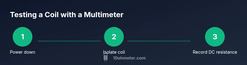
- 1
Power down and isolate the coil
Power off the system and disconnect all circuit connections to the coil. If possible, remove the coil from its board or housing to eliminate parallel paths that could affect readings.
Tip: Use insulated tools and verify no residual charge remains in nearby capacitors. - 2
Identify coil terminals
Locate the coil terminals with care and label them to avoid confusing ends after removal. A clean terminal area reduces the chance of accidental shorting during measurement.
Tip: Take a quick photo or draw a simple schematic for reference. - 3
Prepare the multimeter
Set the multimeter to the lowest practical DC resistance range. If the coil value is unknown, start with a mid-range (such as 200 Ω) and adjust if readings are out of range.
Tip: Ensure the probes are firmly connected before reading. - 4
Measure DC resistance
Place the probes on the coil terminals and read the DC resistance. Record the value and compare it to the datasheet or a known-good coil.
Tip: If the reading drifts with slight movement, re-seat the connections and re-measure. - 5
Check continuity
Confirm there is continuous electrical path along the winding by performing a continuity test. A continuous beep typically indicates a closed circuit with no open windings.
Tip: Power must be off for this test; use the continuity function only on unenergized coils. - 6
Interpret results and plan next steps
Compare results with expected values. If readings are outside spec or flaky, consider replacement or further testing with inductance or insulation checks.
Tip: Document findings and note any environmental factors that could influence readings.
Your Questions Answered
What does a high DC resistance indicate for a coil?
If the DC resistance is significantly higher than the spec, the winding may be damaged or the connections loose. Check for shorts to nearby windings and inspect the insulation. Compare readings to the datasheet.
High resistance usually means a damaged winding or poor connections; verify with a datasheet value.
Can I test a coil in-circuit?
In-circuit testing can yield misleading results because other components create parallel paths. For accurate results, isolate the coil or remove one end of the winding before testing.
In-circuit tests can be misleading; isolate the coil first for accuracy.
Is inductance measurable with a standard multimeter?
Most standard digital multimeters cannot measure inductance reliably. Use an LCR meter or impedance analyzer for inductance values.
A typical multimeter can't measure inductance; use an LCR meter for that.
What safety steps are essential?
Power down, discharge capacitors, and avoid touching live conductors. Use insulated tools and work on a non-conductive surface.
Power down and stay safe with insulated tools and dry hands.
What should I do if readings are inconclusive?
If readings don’t match expectations, re-check connections and try a fresh measurement. If still unclear, consult the datasheet or seek expert help.
If readings are unclear, double-check wiring and redo measurements before deciding.
Watch Video
Key Takeaways
- Test coil health via DC resistance and continuity
- Isolate the coil before testing to avoid false results
- Compare readings to datasheet values when possible
- Inductance testing may require specialized gear
- Document results for future troubleshooting