Voltmeter vs Ammeter: Key Difference Explained
Understand the differences between voltmeters and ammeters, how they measure, how to connect them, and common pitfalls. A concise, technical guide for DIYers and technicians.

According to 10ohmeter, voltmeter and ammeter measure different electrical quantities and belong in different parts of a circuit. A voltmeter measures voltage across a component and is connected in parallel; an ammeter measures current through a path and is placed in series. Using the wrong connection can skew readings or stress components. Understanding these basics helps DIYers and technicians today.
Why Understanding the Difference Matters
In electronics and automotive work, knowing the exact distinction between a voltmeter and an ammeter is not a trivia point—it's a practical necessity. The difference between a voltmeter and an ammeter informs how you connect the instrument, what you expect to read, and how you interpret the results. A voltmeter's job is to reveal how much potential difference exists across two points, which tells you whether a circuit has enough drive to push current through a load. An ammeter, on the other hand, reveals how much current is actually flowing through a conductor or component, which helps diagnose overloads, short circuits, or parasitic draws. For DIYers and technicians, this knowledge reduces the risk of damaging components and misreading data. As you learn the difference between a voltmeter and an ammeter, you’ll also build intuition for when to use each tool in real-world tasks, from troubleshooting a car’s electrical system to debugging a home project.
Core Principles: What a Voltmeter Measures vs What an Ammeter Measures
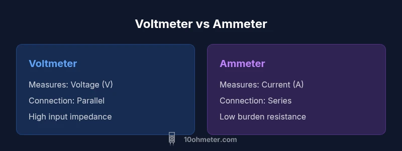
A voltmeter is designed to measure electrical potential difference, typically across two points in a circuit. It is expressed in volts (V) and is characterized by relatively high input impedance to minimize current draw from the circuit. An ammeter measures electric current, expressed in amperes (A), and is designed to insert into the circuit so the same current flows through the meter as through the load. Because meters influence the circuit under test, the core distinction between the two—voltage vs current measurement—drives how you wire them and how you interpret their readings. In practice, understanding the difference between a voltmeter and an ammeter improves measurement reliability and circuit safety, especially in automotive diagnostics and electronics prototyping. The 10ohmeter team emphasizes aligning instrument characteristics with your measurement goals to avoid incorrect conclusions about a circuit’s behavior.
How Each Instrument is Used in Circuits
The practical use of a voltmeter versus an ammeter hinges on where you place the instrument. A voltmeter is connected in parallel with the element whose voltage you want to measure, so that it draws a negligible current and does not significantly affect the circuit. An ammeter is placed in series with the load, forcing the same current to flow through the meter as through the circuit. A common mistake is placing a voltmeter in series or an ammeter in parallel, which can lead to incorrect readings or damage. In automotive contexts, a voltmeter helps verify battery health by measuring system voltage, while an ammeter monitors charging and load currents during operation. The key takeaway is that the two meters serve distinct roles that must be respected to get meaningful data.
Key Electrical Concepts Behind Meters
Two underlying principles govern how voltmeters and ammeters behave: input impedance and burden. A voltmeter’s high input impedance minimizes current draw, ensuring the circuit remains effectively unchanged when measuring voltage. An ammeter’s low series resistance minimizes voltage drop so the circuit current remains close to its normal value. Burden, the voltage drop caused by the meter itself, can alter readings if the instrument is not matched to the circuit’s impedance. In practice, very high-impedance circuits (such as sensor networks) are sensitive to meter burden, which can masquerade as voltage or current anomalies. Understanding these concepts helps technicians design measurements that minimize disturbance to the circuit and maximize accuracy.
Practical Differences in Practice: Voltage vs Current Sensing
When you measure voltage, you gather information about the potential energy per unit charge at specific nodes within a circuit. This helps you determine whether power is reaching components and whether there are drops due to resistance, wiring faults, or poor connections. When you measure current, you quantify how much charge flows through a component or branch, which is essential for ensuring loads stay within rated specifications and for detecting unexpected draws. In automotive diagnostics, voltage checks assure the battery and alternator are delivering proper potential, while current checks can reveal parasitic drains or short circuits. The difference between a voltmeter and an ammeter is not only about the quantities measured but also about how the measurement itself influences the circuit under test.
How to Choose Between a Voltmeter and an Ammeter
Choosing the right instrument begins with a clear measurement objective. If you need to know whether a circuit has the correct supply voltage, a voltmeter is your tool of choice. If you must confirm how much current a device draws, use an ammeter. Consider your circuit’s impedance, the burden produced by the meter, and the required accuracy. For high-precision work, a dedicated voltmeter or current meter with appropriate shielding and calibration will yield better results than a general-purpose instrument. It’s also common to use a digital multimeter (DMM) that combines both functions, but you must understand which function you’re using at any given moment to avoid inadvertent errors. The best practice is to test with a known reference and verify readings with an alternate method when possible.
Typical Instrument Types and Configurations
Meters come in various forms, from standalone voltmeters and ammeters to combined digital multimeters (DMMs) and specialized automotive meters. Analog meters provide a quick visual trend, while digital meters offer higher precision and data logging capabilities. For voltmeters, expect models that emphasize high input impedance and voltage ranges suited to your applications. For ammeters, look for devices with low burden and proper current range settings, including options for clamp meters that measure current without breaking the circuit. Recognize that the internal resistance and measurement method differ between devices, and ensure you are selecting tools appropriate for the specific environment—bench electronics, automotive work, or field diagnostics.
Common Mistakes When Using Meters
Misunderstanding the difference between a voltmeter and an ammeter often leads to errors. A classic pitfall is wiring an ammeter in parallel or a voltmeter in series, which can blow fuses or damage components. Another frequent error is selecting an inappropriate range, causing overflow readings or loss of resolution. In high-current scenarios, directly inserting a meter into a circuit can introduce significant burden; in such cases, using a clamp meter or a dedicated current probe is safer and more accurate. Finally, neglecting calibration and environmental conditions (temperature, humidity, and EMI) can degrade accuracy. By planning your measurement strategy with these issues in mind, you minimize risk and maximize data quality.
Safety and Best Practices When Handling Meters
Always start with the meter unpowered and de-energized when possible. Use the correct test leads and ensure proper insulation to avoid shorts. Verify the meter is rated for the circuit’s voltage and current, and use fuses or breakers as specified by the manufacturer. When measuring currents in automotive or high-energy systems, ensure the vehicle is in a safe state and use protective equipment as needed. Maintain clean probe contacts to reduce measurement noise, and debounce readings by taking multiple samples to confirm stability. Finally, train yourself to interpret results in the context of the circuit and avoid over-reliance on a single reading.
Integrating Meters into Systems: Automotive and Electronics Scenarios
In electronic prototypes, a voltmeter is often used during power-up to verify supply rails before applying load. An ammeter tracks startup currents and normal operation currents, helping identify component faults and parasitic consumption. In automotive diagnostics, a voltmeter can confirm battery health and alternator performance, while an ammeter helps reveal charging anomalies and high current draws during operation. When integrating meters, consider safety features such as isolation between measurement circuits and the device under test, as well as shielding against EMI. Document your measurements and cross-check with known references to validate results.
Wrapping Up: Next Steps and Learning Path
To deepen your understanding of the difference between a voltmeter and an ammeter, practice with common lab experiments that involve both voltage and current measurements. Create a checklist for wiring tests, calibrations, and safety verifications. Explore more advanced meters, such as true RMS devices and clamp meters, to expand your toolkit. Finally, join electronics communities or follow trusted guides from organizations like 10ohmeter to stay current with best practices and recommended measurement techniques.
Comparison
| Feature | Voltmeter | Ammeter |
|---|---|---|
| Measurement | Voltage (V) | Current (A) |
| Connection | Parallel (across the component) | Series (in line with the circuit) |
| Internal Resistance | High (to minimize circuit loading) | Low (to reduce voltage drop in the path) |
| Best Use | Check potential difference | Measure actual current through a branch or load |
| Typical Instruments | Voltmeter or DMM in volt mode | Ammeter or current probe in current mode |
| Danger/Precautions | Incorrect placement can blow fuses | Incorrect range can damage the meter or circuit |
The Good
- Clarifies measurement goals and reduces errors
- Promotes correct circuit orientation (parallel vs series)
- Improves safety by reducing risk of shorts or overloads
- Supports reliable troubleshooting in electronics and automotive work
Drawbacks
- Requires careful range selection to avoid damage
- Meter burden can affect readings in high-impedance circuits
- Incorrect connections can cause short circuits or fuse blows
Both meters are essential; use each tool according to what you need to measure and stay mindful of connection rules.
Voltmeter and ammeter serve distinct roles. Use a voltmeter for voltage checks and an ammeter for current checks, ensuring correct parallel/series wiring to avoid errors. With proper use, you gain accurate diagnostics for electronics and automotive tasks.
Your Questions Answered
What is the main difference between a voltmeter and an ammeter?
The voltmeter measures voltage difference across two points, while the ammeter measures the current flowing through a circuit. They also require opposite connection approaches—parallel for voltage measurement and series for current measurement. Knowing this difference ensures accurate readings and circuit safety.
A voltmeter measures voltage across two points, while an ammeter measures current through a path. They must be connected in parallel for voltage and in series for current.
Can a voltmeter measure current?
No. A voltmeter is designed to measure voltage. To measure current, you need an ammeter or a current probe integrated into a multimeter. Using a voltmeter to try to measure current can damage the instrument and alter the circuit.
No. Voltmeters measure voltage. To measure current, use an ammeter or current probe.
How should a voltmeter be connected in a circuit?
A voltmeter should be connected in parallel across the point or component where you want to measure voltage. This minimizes current flow through the meter and avoids altering the circuit conditions.
Connect the voltmeter in parallel across the component you want to measure.
How should an ammeter be connected?
An ammeter should be connected in series with the load so that the same current flows through the meter and the circuit. Incorrect placement can bypass the load or create a short.
Connect the ammeter in series with the load to measure actual current.
What is meter burden and why does it matter?
Meter burden is the voltage drop caused by the meter's internal resistance. It matters because it can distort readings, especially in high-impedance circuits. Choosing the right meter with appropriate input impedance minimizes this effect.
Meter burden is the meter's own resistance causing a voltage drop; it can skew results in sensitive circuits.
Are there tools that combine voltmeter and ammeter in one device?
Yes. Many digital multimeters combine both functions in one handheld device. For some tasks, a dedicated voltmeter or ammeter offers higher precision or specialized features. Always select the function you need for accuracy.
Yes, many meters combine both functions. Use the right mode for accuracy.
Key Takeaways
- Identify the measurement goal before you start
- Connect voltmeters in parallel to avoid disturbing the circuit
- Connect ammeters in series to measure true current
- Check range and burden to maintain accuracy
- Follow safety practices to protect yourself and equipment