Test Starter Relay with Multimeter: A Step-by-Step Guide
Learn to test a starter relay using a multimeter. This 10ohmeter guide covers coil continuity, contact testing, safety, and common failure modes for DIY electronics and automotive work.

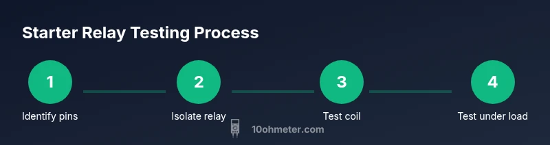
To test a starter relay with a multimeter, locate the relay and its coil terminals, then use the multimeter to check coil continuity and resistance. Next, energize the coil momentarily and verify that the contacts close; finally, test the high-current circuit under load to confirm proper operation. This approach isolates coil and contact faults.
Understanding the test objective and what you’ll measure
Testing a starter relay with a multimeter is a practical way to distinguish coil faults from worn or pitted contacts. The goal is to verify two distinct parts of the relay: the coil, which energizes to pull the switch, and the switch contacts, which carry the high-current load. A clean test helps you decide whether the relay is healthy, needs cleaning, or should be replaced. In DIY and professional repair scenarios, this method reduces guesswork and speeds up diagnostics. According to 10ohmeter, relays fail most often due to degraded contacts or intermittent contacts rather than a damaged coil. By examining both coil continuity and contact behavior, you gain a reliable, repeatable assessment that translates into safer, more dependable electronics and automotive work.
Safety and planning before you begin
Before you touch any wiring, prioritize safety. Disconnect the battery or power source to prevent arcing and accidental energization. Work in a dry, well-ventilated area and wear eye protection and insulated gloves when handling electrical components. Create a simple test plan: identify the relay pins, verify you can isolate the relay, and outline how you will test the coil and the switched circuit. If you are unsure about a vehicle's electrical system, consult the repair manual or seek supervision from a qualified technician. This planning reduces the risk of damage to the relay, wiring harness, or power source and helps you stay organized during the test.
Tools and materials you’ll need
Gather a few essential tools to perform a safe and thorough test. You’ll want a reliable multimeter with continuity and resistance measurement, test leads with probe tips, a spare or known-good relay for comparison, a clean workspace, and a small bench power supply or a controlled 12V source for energizing the coil. Have jumper wires handy to make quick, temporary connections, and keep a spare fuse and safety equipment nearby. If you are testing in a vehicle, you may also need wire cutters, a harness adapter, and a service manual for pinout diagrams.
Step 1: Locate the relay and identify pins
Relays come in several configurations, but most automotive relays have a coil pair and a set of switch contacts. Your first task is to locate the relay in the harness or on the board and identify the coil terminals versus the load terminals. When possible, refer to the relay’s datasheet or the vehicle's service manual for the pinout. If you don’t have documentation, use a systematic approach: test for continuity across two pins that correspond to the coil, then identify which pins connect to the load circuit. This step ensures you’re testing the right parts of the relay and avoids misinterpretation later on.
Step 2: Remove or isolate the relay from the circuit
For an accurate bench test, isolate the relay from the rest of the circuit. This means disconnecting the relay’s harness or removing the relay from the mount if feasible. Isolation prevents other components from influencing readings, such as nearby coils or wiring resistance. If you must test in-circuit, ensure you understand which paths can be safely de-energized and which readings will be affected by the surrounding circuitry. Document the pin connections before removing anything so you can reassemble correctly.
Step 3: Test the coil for continuity
Set the multimeter to the resistance or continuity function and measure across the two coil terminals. A healthy coil generally shows a continuous path (not open) with a finite, lower resistance than an open circuit. If the reading is infinite or very high, the coil may be open or damaged. If your multimeter has a beeper, a steady tone indicates a closed coil circuit. Compare your observed reading with the relay’s datasheet or a known-good relay of the same type to gauge whether the coil is within expected ranges.
Step 4: Energize the coil and observe the switch action
With a safe, current-limited supply, energize the coil terminals briefly to simulate the control signal. You should observe the switch contacts moving and changing the continuity path of the high-current circuit. If your setup allows it, measure continuity across the load contacts both when the coil is de-energized and when it is energized. The switch side should show no continuity when de-energized and should close (conduct) when energizing the coil. If the coil energizes but the contacts do not close, the relay mechanism may be gummed or worn and require replacement.
Step 5: Test the contacts under load
To simulate real-world operation, apply a light load to the contact circuit while the coil is energized. A small lamp or resistor can serve as a safe dummy load. Check that the load path conducts when the coil is energized and stops conducting when the coil is de-energized. If the contact path is erratic or partially conducting, the contacts may be worn or pitted, indicating the relay should be replaced or repaired. Always ensure the load is within safe current ratings for the test setup.
Step 6: Reinstall and verify in the circuit
Once testing is complete, reinstall the relay into its proper position and reconnect harnesses as required. Re-test the circuit under normal operating conditions to confirm the relay performs as expected within the full system. If possible, perform a final field test under typical load conditions to observe how the relay behaves in-service. Document the outcomes for future maintenance records and reference. Proper reassembly minimizes micro-arcing and electrical noise during operation.
Step 7: Interpret results and decide on replacement
If the coil shows good continuity and energizes cleanly but the contact path remains unreliable under load, the relay is likely worn and should be replaced. If the coil shows high resistance or no continuity, the coil is defective and the relay should be replaced regardless of the contact condition. In some cases, intermittent behavior may suggest harness or connector issues rather than the relay itself; inspect connectors for corrosion, tightness, and proper seating. A clear diagnostic path helps you avoid unnecessary replacements and supports reliable performance.
Tools & Materials
- multimeter with continuity and resistance modes(Prefer a meter that can beep on continuity and read stable resistance.)
- test leads and alligator clips(Longer leads help reach relay pins without disturbing the circuit.)
- spare starter relay (for comparison)(Optional but helpful for bench comparison.)
- bench power supply or regulated 12V source(Use current-limiting or fuse-protected supply; never exceed rated coil current.)
- jumper wires(Assists in quick, temporary connections to coil and load circuits.)
- safety equipment (gloves, eye protection)(Always protect yourself during electrical testing.)
Steps
Estimated time: 25-45 minutes
- 1
Identify pins and pinout
Look up the relay’s pinout and distinguish coil pins from load pins. Confirm whether you’re dealing with a four-pin, five-pin, or larger relay, and note which pins correspond to the coil and which to the switch contacts. This ensures you test the right parts and avoid misinterpretation.
Tip: If there’s any doubt, compare against a known-good relay of the same type. - 2
Isolate the relay
Disconnect the relay from the circuit to prevent interference from other components. If removal isn’t feasible, ensure you can safely isolate the coil path from the load path for isolated measurements.
Tip: Label wires before disconnecting to simplify reassembly. - 3
Test coil continuity
Set the meter to continuity or resistance and measure across the coil pins. A healthy coil shows continuity and a relatively low resistance compared with an open circuit. No continuity signals a defective coil.
Tip: If your meter shows a vague or fluctuating reading, recheck connections and clean any corrosion on terminals. - 4
Energize the coil and observe the switch
Briefly energize the coil using a current-limited supply and watch or measure the change in the load circuit. The switch should close when energized and open when de-energized.
Tip: Keep energization brief to avoid overheating or arcing in a test setup. - 5
Test the load path under light load
With the coil energized, apply a safe, light load and verify current flows through the load path. When de-energized, the load path should cut off. Inconsistent behavior indicates worn contacts.
Tip: Use a harmless, low-current load to avoid damaging the relay during testing. - 6
Reinstall and test in circuit
Reconnect the relay to the harness or mount and perform a normal system test. Ensure the relay reliably switches under actual operating conditions.
Tip: Securely seat the relay and verify the harness terminals are clean and tight. - 7
Interpret results and decide on replacement
If coil reads fine but contacts are unreliable, replace the relay. If coil is open or stuck, replacement is recommended. Document findings for future reference.
Tip: When in doubt, err on the side of replacement to avoid unpredictable behavior.
Your Questions Answered
What is the main purpose of testing a starter relay with a multimeter?
Testing helps determine whether the problem is in the coil or the switch contacts, allowing accurate replacement decisions and preventing unnecessary work on the motor or wiring.
Testing a starter relay with a multimeter helps you tell if the coil or the contacts are at fault, so you know exactly what to replace.
Can I test a relay without removing it from the vehicle?
Yes, but it can be more challenging due to wiring and other components. Isolate the coil path when possible and proceed with caution to avoid interference from surrounding circuitry.
You can test it while installed, but isolation and careful probing are key to accurate results.
What readings indicate a bad coil?
A coil that shows no continuity or an unusually high resistance suggests a bad coil. Compare your readings with a known-good relay if possible.
No continuity or very high resistance means the coil is likely bad.
Should I test the relay under load?
Testing with a light load on the contact circuit provides a realistic assessment of performance. Absence of proper closure under load indicates worn contacts.
Yes, load testing helps confirm the relay can carry the intended current.
What if readings don’t match expectations?
If measurements don’t align with the expected behavior, verify connections, re-test, and consider replacing the relay or checking the controlling circuit for faults.
If the numbers don’t add up, double-check connections and consider replacement if symptoms persist.
Watch Video
Key Takeaways
- Test both coil and contacts to isolate faults
- Use isolated bench testing before in-circuit work
- Energize briefly with a safe power source
- Replace relays exhibiting wear or open coils