Test Relay with Multimeter: Step-by-Step Guide for Reliable Switching
Learn how to test a relay with a multimeter, covering coil resistance, contact continuity, and switching action. Practical, safe methods for electronics and automotive relays. Includes step-by-step instructions, tips, and authoritative sources.

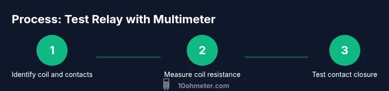
Power down the circuit, locate the relay, and identify coil and contact terminals. Use a multimeter to measure coil resistance and verify it matches the datasheet. Check each contact for continuity in both energized and de-energized states to ensure proper switching. If readings are off, replace or reseat the relay and retest. Document any abnormal results for warranty or diagnostics.
Why test a relay with a multimeter
Testing a relay with a multimeter helps you quickly verify whether the coil is healthy and the contacts switch cleanly. Whether you’re diagnosing a noisy automotive relay or a stubborn timer relay in a home project, a few careful measurements can spare you hours of guesswork. According to 10ohmeter, testing relays with a multimeter is a practical skill for DIY enthusiasts and technicians learning to use multimeters for electronics and automotive tasks. This article walks you through coil health checks, contact integrity tests, and how to interpret results. You’ll learn how to differentiate coil faults from worn contacts and decide when a relay should be replaced rather than retried. When you know what to check, you can triage quickly and keep your circuits reliable.
In practice, the test focuses on three core areas: coil resistance, contact continuity, and switching action. The coil should show a predictable resistance value within the coil’s rating; contacts should be open in one state and closed in the other; and the switch should respond promptly without hesitation or chatter. The goal is to confirm that the relay can reliably energize and isolate the load as designed. With the right setup and safety cadence, you can confirm fundamentals and locate faults with confidence.
Brand context and practical mindset
Throughout electronics and automotive projects, relays are the gatekeepers of safe, isolated switching. A disciplined test not only confirms current viability but also informs maintenance decisions. The 10ohmeter team emphasizes building a repeatable testing routine that you can apply to many relay types, from small signal relays used in hobby projects to automotive power relays that control heavier loads. By adopting a consistent approach, you’ll reduce debugging time and improve long-term reliability.
Defining success: what a good test looks like
A successful relay test demonstrates three things: a healthy coil that reads within spec, contact paths that open and close as expected, and a clean switch action without sticky or noisy behavior. If any of these fail, you should investigate further—checking for coil shorts, welded contacts, corrosion, or mechanical sticking—and replace the relay if needed. Documentation of readings provides a traceable record for future maintenance or warranty purposes.
Safety-first framing for every test
Safety is non-negotiable when testing relays, especially in automotive or mains-powered circuits. Always disconnect power, discharge capacitors, and verify there is no voltage present at the test points. Use insulated tools, keep your work area dry, and never bypass protection features just to get a reading. A careful, methodical approach protects you and extends the life of the relay and surrounding circuitry.
Why coil health matters for reliability
Coil health directly impacts switching reliability. A coil that draws excessive current or shows high resistance can fail to energize the contacts reliably, leading to intermittent operation or latch-up. By validating coil resistance against the datasheet and comparing it to a known-good unit when available, you reduce guesswork. This habit is especially valuable when diagnosing intermittent faults that appear only after heating or vibration.
Tools & Materials
- Digital multimeter (with resistance and continuity mode)(Set to ohms for coil tests; use continuity for fast path checks.)
- Test leads with alligator clips(Attach securely to terminals without stressing the relay pins.)
- Small screwdriver set(To gain access to relay terminals and label connections.)
- Bench power supply or 12V DC source(Provide correct coil voltage; limit current to safe levels.)
- Known-good relay or datasheet(Useful for cross-checking readings against a reference.)
- Insulated workspace and safety gear(Safety goggles and dry environment.)
Steps
Estimated time: 25-45 minutes
- 1
Power down and isolate the circuit
Turn off all power sources and unplug the device. If the relay is in a powered circuit, disconnect the harness to prevent backfeed. This ensures your readings reflect the relay alone and keeps you safe from shocks.
Tip: Use a non-contact tester to verify no mains voltage is present before touching the circuit. - 2
Expose the relay terminals
Remove the relay cover or access panel to reveal coil terminals and the normally open (NO) and normally closed (NC) contacts. Label each terminal to avoid mix-ups during testing and reassembly.
Tip: Photograph the wiring before disconnecting anything for future reference. - 3
Measure coil resistance
With the relay isolated, place the multimeter probes on the two coil terminals and read the resistance. Compare this to the datasheet value for your relay’s coil voltage rating. A reading that is open or wildly out of spec indicates a damaged coil.
Tip: If you see an overrange reading, do not apply power; coil may be damaged. - 4
Test coil energization (safe voltage)
Connect the coil to a safe, voltage-limited supply equal to its rated voltage. Listen for a solid click and feel for any mechanical sticking. If the relay does not energize, stop and verify wiring and coil condition.
Tip: Always limit current and never apply more than rated voltage to the coil. - 5
Check contact continuity in both states
With the coil de-energized, test NO and NC contacts for continuity. Energize the coil and re-test. The NO path should close and the NC path should open when the relay switches. Note any contacts that remain unchanged or show erratic readings.
Tip: Be sure to test each contact pair separately to identify welded or pitted contacts. - 6
Reassemble and perform a functional check
Reassemble the relay into its socket or circuit and power the system. Observe whether the relay reliably controls the intended load under typical operating conditions. Document results for future reference.
Tip: If any performance anomalies appear, replace the relay with a known-good unit and re-test.
Your Questions Answered
What is the best way to test relay coil resistance with a multimeter?
Set the multimeter to ohms, place probes on the coil terminals with the circuit isolated, and compare the reading to the relay’s datasheet. A reading that is open or far outside spec indicates a damaged coil. If uncertain, test against a known-good relay of the same model.
Use the ohms setting to measure the coil directly, then compare to the datasheet or a known-good unit. An open reading means a failed coil.
Can I test a relay without removing it from the circuit?
You can test in-circuit, but readings may be affected by other components. When possible, remove the relay or isolate it to get clean coil resistance and contact readings.
In-circuit tests work, but can be skewed by surrounding parts; removing the relay gives the cleanest data.
What safety steps should I take before testing a relay?
Power down and unplug the device, discharge capacitors, and verify no voltage at test points before touching terminals. Use insulated tools and wear eye protection.
Always ensure the circuit is de-energized and safe to touch before testing.
Why might a relay click but fail to switch a circuit?
The coil may energize but contacts could be welded, pitted, or coated with corrosion. In such cases, the relay needs replacement or proper cleaning/reconditioning.
A click alone isn't enough; inspect the contacts for wear or welding.
Should I replace a relay if coil resistance is out of spec?
Yes. If coil resistance is out of the datasheet range, the coil is likely degraded. Confirm with a known-good unit if possible, and replace if readings don’t align.
If the coil resistance is wrong, replace the relay rather than guessing.
Is this testing method suitable for automotive relays?
Yes, with caution: use the correct coil voltage, verify insulation, and test outside the harness when possible to avoid shorting the vehicle’s systems.
Automotive relays can be tested similarly, but always match coil voltage and practice safety around the vehicle.
Watch Video
Key Takeaways
- Test coil health early to rule out coil faults.
- Verify both NO and NC contact behavior for reliable switching.
- Compare readings to datasheet or known-good relays.
- Isolate the relay during testing to avoid circuit interference.
- Document results for maintenance and warranties.