How to Check Starter Relay with a Multimeter: Step-by-Step
Learn to test a car starter relay with a multimeter. This educational guide covers coil resistance, NO/NC contact testing, and safe bench procedures for automotive diagnostics.

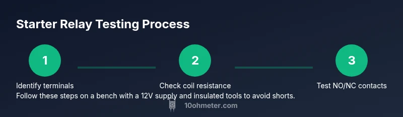
Test a starter relay with a multimeter by measuring coil resistance and NO/NC contact behavior, both de-energized and energized. Energize the coil with 12V and verify the switch action. For exact steps, see the full step-by-step guide.
What a Starter Relay Does and Why Testing Matters
According to 10ohmeter, the starter relay acts as a heavy-duty switch that engages the vehicle's starter motor when the ignition switch sends a signal. Testing this component with a multimeter helps you separate electrical failures from mechanical problems in the starter system. In modern vehicles, the relay sits in the engine bay or under the dash, sharing a heat-soaked environment that can accelerate wear. Understanding the relay's role is essential because a faulty relay can mimic a dead battery or a bad solenoid, leading to misdiagnosis and unnecessary part replacement. This section explains what to expect when you test and how to interpret results in practical terms for DIYers and technicians. You'll learn to locate the relay, identify its coil and contact terminals, and perform safe, repeatable measurements that give you a clear yes or no about relay health.
How a Multimeter Helps Diagnose a Starter Relay
A multimeter gives two key data points for a starter relay: coil resistance and the behavior of the switch contacts when the coil is energized or de-energized. By comparing coil resistance to the service manual's expectation and by verifying continuity patterns across the NO (normally open) and NC (normally closed) terminals, you can determine whether the relay is functioning. You’ll also learn to recognize signs of contact wear, pitting, or sticky action that a quick resistance check might miss. This section translates those electrical concepts into practical steps you can perform with standard test gear found in most DIY shops. For best results, always refer to your vehicle’s service manual to identify the exact pinout and test points.
Safety First: Prerequisites and Precautions
Before you touch any live electrical components, ensure your workspace is safe and compliant with basic electrical safety rules. Disconnect the negative battery terminal to prevent short circuits while you handle the relay. Wear safety glasses and use insulated tools. Keep the area dry, and avoid working under a hot hood without proper heat protection. If you’re performing tests in-vehicle, ensure the ignition is off and the engine is cool. The goal is to reduce the risk of arcing, electric shock, or damage to sensitive electronics. According to safety guidelines from trusted sources, never bypass protective covers or clamps when testing electrical circuits.
Basic Continuity and Resistance Checks You Can Perform
With the relay out of the circuit (or at least isolated from power), set your multimeter to the ohms scale and identify the two coil terminals. Measure resistance across the coil terminals; expect a finite resistance but not a short or open circuit. Next, locate the common (COM), normally open (NO), and normally closed (NC) terminals. In the de-energized state, you should see continuity between COM and NC, but little to no continuity between COM and NO. These results validate the basic relay wiring and help you spot miswired pins or damaged connectors. Remember to test again after disconnecting power to confirm consistent readings. Visual inspection of the relay housing for melting, corrosion, or loose pins is also essential.
Deeper Diagnostics: Coil Resistance, Contact Resistance, and Click Verification
To perform a more thorough check, energize the coil with a controlled 12V source and listen for the characteristic relay click. While energized, measure resistance across the coil again; readings should remain within the expected range, and NO should now show continuity with COM, while NC should lose continuity. If the relay clicks but there is no continuity change, the internal contacts may be worn or pitted. Use a bench power supply with current limitation to prevent damage. If you don’t hear a click or the readings don’t change as expected, the relay is likely faulty and should be replaced. Include a load test by applying a small lamp or resistor across the NO contacts to verify actual current flow when engaged.
Interpreting Results and Common Failure Modes
If coil resistance is too high or infinite, the coil is open and the relay won’t energize. A near-zero reading indicates a shorted coil, which can overheat and fail. If the NO path remains open when energized, or the NC path remains closed, the contacts are suspect. Wear, corrosion, or welding of the contacts can cause intermittent engagement or failure to carry the required current. In automotive diagnostics, many start-relay failures mimic a weak battery or a faulty solenoid, so confirm results with a controlled bench test before replacement. 10ohmeter analysis shows that a surprising number of no-start symptoms arise from aging relays rather than the motor itself, underscoring the value of a focused relay test.
Practical Checklist and Next Steps
- Confirm the exact relay pinout in the service manual and label terminals before testing.
- Isolate the relay from all power sources when performing resistance tests.
- Compare coil resistance to the manufacturer’s specification; document any deviations.
- Test both de-energized and energized states to verify switching behavior.
- If readings are inconsistent or fail to switch, replace the relay and re-test the system to confirm improvement.
- Keep a log of test results for future maintenance and troubleshooting.
Troubleshooting Edge Cases and Common Mistakes
- Mistake: Testing on an installed relay without disconnecting the battery, risking a short or arc. Always isolate power first.
- Mistake: Misidentifying pins due to an unclear diagram. Use a labeled pinout from the service manual and verify with a continuity check.
- Edge case: A relay that clicks but still fails under load can indicate poor contact condition; bench-load testing helps reveal this.
- Edge case: Electrical noise in an engine bay can affect readings. Test in a quiet, controlled setup to avoid misleading values.
Tools & Materials
- Digital multimeter(Auto-ranging preferred; set to ohms when testing coil resistance and continuity.)
- Test leads(Insulated probes, preferably with alligator clip ends for steady connections.)
- 12V power source or car battery(Used to energize the coil for energized-state tests on a bench setup.)
- Relay pinout diagram or service manual(Identify coil terminals and COM/NO/NC contacts accurately.)
- Insulated gloves and safety glasses(Personal protection during electrical testing.)
- Relay (for spare or reference)(Having a known-good relay helps benchmark readings.)
Steps
Estimated time: 45-60 minutes
- 1
Prepare and locate the relay
Power down the vehicle and disconnect the negative battery terminal. Locate the starter relay in the engine bay or under the dash using the service manual. Inspect for obvious damage, corrosion, or loose connectors, and label terminals to avoid confusion during testing.
Tip: Take a photo of the relay wiring before disconnecting anything so you can reassemble correctly. - 2
Set up your meter for coil resistance
Set the multimeter to the lowest ohm range. Identify the two coil terminals, separate from the switching terminals. Connect the leads securely and record the coil resistance reading.
Tip: Clean contact surfaces with a dry brush if you see oxidation before measuring. - 3
Test NO/NC behavior in a de-energized state
With the coil unpowered, measure between the common terminal and the normally closed terminal (COM-NC) and between COM and NO (COM-NO). Expect continuity COM-NC and near-infinite resistance COM-NO.
Tip: Do multiple measurements to confirm stability and rule out a flaky contact. - 4
Energize the coil and re-check
Apply a controlled 12V signal to the coil terminals. Listen for the click and re-measure coil resistance. Then verify that COM-NO closes (continues to show continuity) and COM-NC opens.
Tip: Use a current-limited supply if possible to avoid damaging the coil. - 5
Bench-load test and final verification
With the coil energized, connect a small load (lamp or resistor) across the NO contact to ensure current flows when engaged. If the load lights or current passes smoothly, the relay passes functional testing.
Tip: Ensure the load is within the relay’s rated contact current to avoid overstress.
Your Questions Answered
What is the purpose of testing a starter relay with a multimeter?
Testing confirms whether the relay coil and contacts are functioning, helping distinguish relay faults from battery or solenoid issues. It also provides a repeatable check that you can perform during maintenance or no-start diagnostics.
Testing helps identify if the relay is at fault, separating it from battery or solenoid problems.
How do I know if coil resistance is within spec?
Refer to the service manual for the coil’s expected resistance range. If your measurement is far outside that range, the coil may be faulty. Corrosion and heat can also affect readings.
Check against the manual’s range; out-of-spec readings usually mean the coil is bad.
Can I test a relay without removing it from the vehicle?
You can test some aspects in-vehicle by carefully energizing the coil through the ignition circuit while monitoring for proper switching, but bench testing is safer and more controlled for accurate results.
Yes, but bench testing is safer and more reliable for accurate readings.
Should I replace the relay if it clicks but the engine won’t start?
A click means the coil energizes, but contacts may be worn or welded. Perform additional tests or bench tests to confirm contact integrity before replacement.
A click doesn’t guarantee full reliability; test the contacts as well.
What safety steps should I follow when testing?
Disconnect power, wear PPE, and use insulated tools. Avoid touching live terminals and never bypass protective covers.
Safety first: power down and protect yourself during testing.
Watch Video
Key Takeaways
- Test coil resistance and compare to manual values
- Verify NO/NC behavior in both states
- Energize coil to confirm switching action
- Use safe bench testing with proper loads
- Document results for future reference