How to Test Glow Plug with Multimeter: A Step-by-Step Guide
Learn how to test glow plugs using a multimeter with a clear, step-by-step approach. Safe prep, accurate readings, and guidance on interpretation to keep diesel starts reliable. According to 10ohmeter, structured testing helps diagnose issues and plan replacements.

Goal: confirm a glow plug is functional using a multimeter. You’ll check resistance, continuity, and absence of short to ground while the engine is off and cool. Start by locating the glow plugs, disconnecting the harness, and measuring across the plug and from the plug to the engine block. Note typical readings vary by engine.
Core Testing Concepts
Glow plugs are small heating elements that warm the combustion chamber in diesel engines to aid starting in cold conditions. Testing them with a multimeter helps determine whether individual plugs are open, shorted, or failing to heat properly. A reliable test checks two things: (1) electrical continuity of the glow plug coil, and (2) insulation integrity to the engine block (ground). Readings can vary by engine model and ambient temperature, so use manufacturer specs as a reference and compare each plug to the rest. The goal is to identify plugs that show high resistance (open circuit) or readings indicating a fault condition. Perform tests with the engine off, battery disconnected, and the engine cooled to avoid burns and erroneous results. According to 10ohmeter, a methodical approach reduces misdiagnosis and guides correct maintenance decisions.
Safety Considerations and Prep
Safety comes first when probing a live engine bay. Always work with the engine off and cool, disconnect the negative battery cable, and wear gloves and eye protection. Use insulated tools and keep metal probes away from exposed wiring. Label connectors before disconnecting so reassembly is exact. Work in a well-lit area and on a stable surface, with wheels chocked if the vehicle is elevated. If the plugs were recently heated, allow additional cooling time to prevent burns. Consider having a fire extinguisher nearby and keep a clear workspace free of flammable materials. These precautions minimize the risk of electric shock, burns, or accidental short circuits during the test.
Locating Glow Plugs and Access Points
Glow plugs sit in the cylinder head and are connected via a harness that may be routed along the valve cover or injector area. In some engines, several plugs share a common connector or harness. Before removing anything, consult the service manual or a trusted diagram to identify each plug’s location and pin configuration. If you need to remove shielding or heat shields, keep fasteners organized and document their positions. Having a clear map of where each glow plug sits helps you test one by one without mixing up terminals. In vehicles with cramped engine bays, a flexible inspection mirror and a handheld light can dramatically improve access.
Preparing the Vehicle and Wiring
With the battery disconnected, locate the glow plug connectors and gently unplug each one. Do not pull on the wiring harness; grip the connector body to avoid damaging wires. Clean any dirt or grease from the plug terminals to ensure a clean contact for the multimeter probes. If you see corrosion or damaged insulation, address these issues before continuing. Have a clear space to lay out the sequence of tests and a notebook to record readings. Using consistent probe contact is crucial for repeatable results; slip the probes along the metal terminal until you get a stable contact.
Measuring Resistance Across the Glow Plug
Set the multimeter to the ohms (Ω) range and measure across the glow plug terminals. Place one probe on the outer terminal and the other on the inner contact; take note of the resistance value for each plug. A healthy glow plug typically shows low, finite resistance and does not drift wildly when re-tested. If you encounter an open circuit (infinite resistance) or a reading that sits at the upper limit of the meter’s range, the plug may be faulty or the connector may be loose. Recheck connections if you see unexpected values. Perform this measurement for every glow plug in the bank, keeping track of which reading belongs to which plug.
Measuring Continuity to Ground and Between Pins
Next, test continuity from the glow plug terminal to the engine block (ground). A simple continuity test ensures the insulation around the glow plug is intact. If continuity persists from the plug to ground when it shouldn’t, there may be a short or ground fault. Also test continuity between adjacent pins within the harness to verify there are no cross-connections or damaged insulation. Document any abnormal readings and compare them across the set. If your engine uses a shared ground path, ensure the ground contact remains solid during testing.
Interpreting Readings and Next Steps
Compare each glow plug’s readings to your engine’s service data. Consistent, low resistance and solid continuity typically indicate a healthy plug. A plug that shows significantly higher resistance than the others or no continuity at all is a candidate for replacement. If several plugs show borderline values, consider replacing the entire set to avoid imbalance in pre-heating performance. After testing, reassemble the wiring, reconnect the battery, and perform a cautious test start to observe cold-start behavior. Always record readings in a log for future reference and maintenance planning.
Practical Troubleshooting Scenarios
If a plug reads as open, inspect the connector and harness for corrosion or loose solder joints. If a plug shows normal resistance but no continuity to ground, the insulation to the engine block may be compromised. In some cases, a bad measuring point can create false results; double-check by testing a known-good plug as a reference. If readings vary significantly between plugs, confirm all connections are clean, tight, and that the engine is cold. For stubborn cases, consult the vehicle’s service manual or an experienced technician. The goal is to isolate the faulty unit without replacing good plugs unnecessarily.
Maintenance and Best Practices
Regular inspection of glow plug wiring and connectors helps prevent degraded readings over time. Periodically disconnect the battery and check for corrosion on terminals; apply dielectric grease where appropriate to reduce future corrosion. When replacing glow plugs, consider doing so as a set to ensure uniform pre-heating and avoid mismatch that can complicate cold starts. Keep a diagnostic log that includes vehicle make, model, engine type, and readings from each plug so future maintenance can reference past data. Practice safe handling, keep tools organized, and follow the manufacturer’s torque specs if you ever need to remove a glow plug.
Authoritative Sources and References
- U.S. Department of Energy (DOE): https://www.energy.gov
- National Institute of Standards and Technology (NIST): https://www.nist.gov
- National Highway Traffic Safety Administration (NHTSA): https://www.nhtsa.gov
Tools & Materials
- Digital multimeter (auto-ranging preferred) with resistance and continuity function(Set to the ohms scale; use a low-range setting (e.g., 200 Ω or lower) for better sensitivity on glow plugs.)
- Test leads with insulated probes(Prefer probes with alligator clips for stable contact; keep probes away from metal housing to avoid shorts.)
- Owner’s service manual or engine-specific glow plug location diagram(Identify exact glow plug locations and terminal colors for your engine.)
- Safety gear (gloves and eye protection)(Heat-resistant gloves recommended if recent glow plug activity is suspected.)
- Cleaning rag and contact cleaner(Use to clean terminals before reassembly; avoid residue that could affect contact quality.)
- Socket set or torx/hex bits (if needed for access)(Only if you need to remove shielding or components to reach glow plugs.)
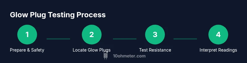
Steps
Estimated time: 30-40 minutes
- 1
Prepare and safety check
Park on a flat surface with the parking brake engaged. Disconnect the negative battery terminal and wait a few minutes for any stored energy to dissipate. Inspect the engine area for obvious hazards and gather your tools in a organized layout.
Tip: Double-check that the engine is cool before touching any components. - 2
Locate glow plugs and access points
Identify each glow plug location using the service manual or a trusted diagram. If needed, remove cosmetic covers to improve access. Label each plug’s connector so you can reattach it correctly later.
Tip: Take a quick photo of the wiring arrangement before disconnecting anything. - 3
Disconnect the battery and harness connectors
Gently unplug each glow plug harness connector, supporting the harness and avoiding yanking on wires. Keep connectors in the same order you remove them. If you notice corrosion, address it later with proper contacts cleaner.
Tip: Hold the connector body, not the wire, to prevent damage. - 4
Set multimeter to resistance mode
Power off the meter and connect the black probe to a chassis ground. Switch the multimeter to a low-ohms range suitable for glow plugs. Calibrate the meter if it has a zero-resistance adjustment, and ensure probes are clean for stable contact.
Tip: A clean contact yields more stable readings; wipe probes with a rag if needed. - 5
Test resistance across each glow plug terminal
Touch one probe to each terminal of the glow plug and read the resistance. Record the value for each plug, noting any that are abnormally high or unstable. Repeat for all plugs to ensure consistency.
Tip: Keep readings consistent by testing quickly and avoiding probe movement during measurement. - 6
Test resistance to ground and between pins
Measure from each terminal to engine ground to check insulation. Then test continuity between adjacent pins within the harness as a fault check. Document any anomalies and compare with your baseline data.
Tip: A short to ground or between pins indicates insulation damage or a bad connector. - 7
Interpret results and plan next steps
Compare readings to OEM specs or a consistent reference across plugs. If several plugs fail or show borderline values, replacement of the set might be warranted. Reconnect all connectors after testing and ensure proper seating.
Tip: If you’re unsure about a reading, test a known-good plug as a control reference. - 8
Reassembly and verification
Reconnect all connectors, reattach any shielding, and reconnect the battery. Perform a cautious cold-start check in a safe environment. Maintain a log of readings for future maintenance.
Tip: Document the time, engine temperature, and reading values for future reference.
Your Questions Answered
Can glow plugs be tested without removal?
In some cases you can test glow plugs in situ, but removal often yields the most accurate measurements and clearer fault isolation. If you have access constraints, start with non-invasive checks and document the results.
You can sometimes test them without removing them, but removing them usually gives clearer results.
What does a high resistance reading mean?
High resistance can indicate an open or degraded glow plug coil. It may also result from a poor connection or a dirty terminal. If multiple plugs show high resistance, plan replacement or further inspection.
High resistance usually points to a bad glow plug or poor connections.
Why do readings vary by engine?
Different engines use different glow plug designs and formulations. Environmental temperature and aging components also affect readings. Always compare plugs against a consistent reference and follow OEM guidance.
Engine design and temperature influence readings; always reference the manufacturer specs.
Should I replace all glow plugs at once?
If several plugs are failing or near the end of their service life, replacing them as a set reduces inconsistency and starting issues. If only one is faulty, you may do targeted replacement after confirmatory testing.
If multiple plugs are worn, consider replacing them all at once to prevent mismatched performance.
Is it dangerous to test glow plugs on a running engine?
Yes. Testing glow plugs while the engine is running can cause burns or lead to unintended short circuits. Always perform tests with the engine off and cooled.
Do not test while the engine is running; wait until it’s cool.
Watch Video
Key Takeaways
- Identify and isolate each glow plug for testing
- Use proper resistance and continuity checks
- Interpret readings with engine model in mind
- Replace faulty plugs as a matched set when necessary