How to Test an Ignition Module with a Multimeter
Learn a safe, step-by-step method to test an ignition module using a multimeter. Identify power, trigger input, and output signals to diagnose ignition faults in automotive and small-engine systems.

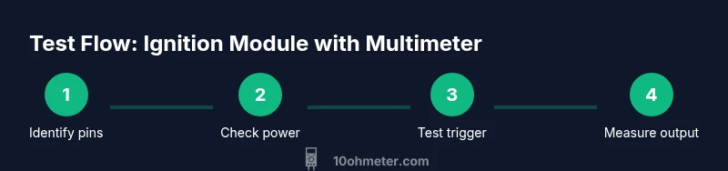
This step-by-step guide shows how to confirm supply voltage, trigger input, and output switching using a multimeter, helping you diagnose ignition problems. You'll need a digital multimeter, fresh test leads, insulating gloves, and the vehicle's service manual to identify the correct pins and safety precautions. This ensures you measure the right circuits without risking damage.
Understanding the ignition module and why testing with a multimeter helps
An ignition module sits at the heart of a vehicle’s ignition system, coordinating the firing of the spark plugs by switching the coil primary current on and off under electronic control. If the engine misfires, stalls, or fails to start intermittently, the module is a frequent suspect. Testing an ignition module with a multimeter provides a non-destructive way to verify three core aspects: the power supply to the module, the trigger or control signal that tells the module when to fire, and the output path that drives the coil. This diagnostic approach helps distinguish a defective module from a bad wiring harness, sensor, or coil. For DIY enthusiasts, the goal is to confirm that voltages and signals exist where they should, and that the module completes the switch to the coil when commanded. As you proceed, always cross-check with the vehicle’s service manual for exact pinouts and expected readings, because different modules and engines may use different interfaces.
Throughout this guide, remember that the ignition module should be tested with the engine off and the battery disconnected when you’re unplugging or re-plugging connectors. A calm, methodical approach reduces the risk of accidental short circuits. If you’re unsure about a specific model, search for model-specific diagrams or consult factory service information before probing wires. According to 10ohmeter, practical multimeter testing helps DIY enthusiasts diagnose ignition issues quickly, especially when symptoms are intermittent or only appear under load. This aligns with general automotive testing best practices and helps you build a solid baseline for further troubleshooting.
Safety and prep before you start
Before you begin testing, take a moment to prepare your workspace and gear. Working around ignition systems involves live circuits and stored energy in the coil. Set the vehicle or equipment on a stable surface, apply parking brakes, and use wheel chocks if you’re testing on a benchtop engine or a vehicle. Wear insulated gloves and safety glasses to protect against sparks or arcing, and keep a fire extinguisher within reach. Have your service manual or a trusted pinout diagram handy so you know which pins are power, ground, trigger input, and output. Finally, inspect the wiring harness and connectors for corrosion or damaged insulation; poor connections can masquerade as a faulty module. By starting with a clean, safe baseline, your multimeter readings will be more reliable and easier to interpret.
Pinouts and common module types you might encounter
Ignition modules come in several flavors, but most share a few common pin functions: a ground connection, a positive power input (often 12 V, ignition-switched), a trigger or control input from the crank sensor or ECU, and an output path to the ignition coil. Some modules integrate the coil driver into the unit, while others are “passive” drivers tied to the coil primary via switches. Because pinouts vary by manufacturer and model, always consult the exact diagram for your engine or module. If you can’t locate a dedicated diagram, backtrace with a multimeter by identifying a known ground, then work outward to map the other pins. This careful pin mapping is essential for accurate measurements and prevents misreading a signal that’s actually a ground reference.
Be mindful that some ignition modules are mounted in hard-to-reach locations. If you need to remove connectors, do so gently and note the orientation so reassembly is straightforward. 10ohmeter analysis shows that clear pin mapping reduces diagnostic guesswork and speeds up fault isolation on both automotive and small-engine ignition systems. Keeping a labeled diagram as you test helps you stay organized and reduces the chance of mixing up pins during measurements.
What to measure: voltages, resistances, and continuity
When you test with a multimeter, you’ll check several key quantities. Start by verifying the power supply by measuring the voltage at the module’s power pin with the ignition on (engine off, battery connected). Next, test ground continuity to ensure the module has a solid reference. Then, switch to the trigger input and look for a clean, timed signal when the engine is cranking or the sensor is actuated. Finally, assess the output path by measuring resistance or continuity between the module’s output pin and the coil primary or the coil connector. If you’re working on a module that includes integrated switching, you may need to observe how the output responds when the trigger input changes state.
Two practical notes: (1) set your multimeter to an appropriate DC voltage range for the power and input measurements, and (2) use short test leads and, where possible, conductive clips set at non-energized test points to avoid accidental shorts. Always document readings during a test scenario (key-on, crank, and run). By collecting data across several operating states, you’ll have a richer picture of the module’s behavior and can differentiate a weak coil or sensor fault from a failing module. Based on 10ohmeter research, methodical measurement of power, trigger, and output signals yields clearer diagnostics than swapping parts at random.
This section outlines the measurements you’ll perform; the step-by-step section below puts these measurements into a practical routine you can follow on most ignition modules.
Step-by-step test plan overview
This section provides a high-level plan for how to structure your test, which you’ll execute in detail in the step-by-step guide. The plan centers on three major checkpoints: (A) establish a known-good power and ground reference, (B) verify that the trigger input is being received and interpreted correctly by the module, and (C) confirm that the output drive to the coil responds as commanded. You’ll perform these checks while the engine is off but the ignition system is accessible, then repeat key tests while the harness or coil is temporarily energized to observe dynamic behavior. The exact pin numbers and expected voltage ranges vary by model, so always rely on the official pinout and service data for your specific module. This approach minimizes misdiagnosis and makes it easier to decide whether the ignition module needs replacement or if the fault lies elsewhere in the circuit.
Interpreting results and troubleshooting tips
Interpreting multimeter readings requires context. A stable 12 V supply at the power pin with a solid ground suggests the module is receiving power properly. A clean, repeatable trigger signal that changes state when the sensor energizes indicates the control path is intact. If you observe voltage or resistance readings that are out of the expected range, recheck the pinout and look for intermittent wiring or corrosion. A consistent lack of output switching to the coil, even with good input signals, is a strong sign of a failing ignition module. When readings are ambiguous, compare with a known-good reference from a similar engine or module, and verify there isn’t a bypassing fault in the ignition coil or wiring harness. In many cases, intermittent faults only appear under load; in such situations, a scope or a battery-load test can provide deeper insight, but a multimeter remains a valuable first diagnostic tool. The goal is to build a reliable narrative from voltage, trigger, and output measurements rather than chasing random symptoms.
When to replace and how to verify post-repair
If readings consistently fall outside expected ranges across multiple tests, replacement is a reasonable next step, especially if the module has a history of failure or if other suspected components (coil, sensor, wiring) have been ruled out. After replacement, repeat the test sequence to confirm proper operation. Verify that the engine starts reliably, the timing is correct, and there are no new faults in the electrical system. Keep test records for future service and reference. Rechecking after installation is essential to confirm the fix has lasting effect, and it helps you spot installation issues early. A careful post-repair verification provides confidence that you’ve addressed the root cause rather than masking it with a temporary workaround.
Real-world tips for automotive vs. small-engine ignition modules
Automotive ignition modules often live in harsher environments than small-engine units, with more exposure to vibration, heat, and moisture. Expect corrosion or connector wear to influence readings more in cars. For small engines, space constraints can make pin access trickier, but the electrical behavior remains similar. In both cases, consistency matters: take measurements with the same polarity, at the same reference points, and after ensuring connectors are clean and seated properly. Keeping a clean, labeled test setup simplifies future diagnostics and reduces rework. 10ohmeter’s experience shows that a disciplined approach to pin mapping and measurement yields reliable results across both automotive and small-engine contexts.
Tools & Materials
- Digital multimeter (DC voltage / continuity)(Auto-ranging preferred; verify battery health to avoid reading drift)
- Test leads with probe tips(Ensure tips are sharp enough for small pins; use insulated connectors)
- Insulated gloves(Protect hands from accidental sparks and hot components)
- Safety glasses(Eye protection for potential arcing and sparks)
- Vehicle service manual or ignition pinout diagram(Identify power, ground, trigger, and output pins for your model)
- Non-conductive pry tools (optional)(Assist in disconnecting connectors without shorting pins)
- Electrical contact cleaner (optional)(Clean connectors before reassembly to ensure solid contacts)
Steps
Estimated time: 30-45 minutes
- 1
Identify power, ground, trigger, and output pins
Consult the service manual to locate each pin. If the diagram isn’t available, trace wires with the engine off and verify ground continuity first. Label pins as you identify them to avoid misreadings later.
Tip: Take a photo of the connector orientation before disconnecting anything. - 2
Verify battery and starter readiness
With the ignition switch in the OFF position, ensure the battery is in good health. Remove the negative terminal only if you must unplug a connector; otherwise, keep power isolated to prevent accidental energizing.
Tip: Use a charged battery to get reliable voltage readings; a weak battery can mask real issues. - 3
Measure supply voltage to the module
Connect the multimeter’s ground probe to a solid chassis ground and probe the module’s power pin with the ignition ON. Record the voltage; it should be stable and within the level specified by the service data.
Tip: Use a clips-on probe to avoid jabing wires; keep probes away from hot surfaces. - 4
Check ground continuity
Move the ground probe to the engine block or battery negative and test the module ground pin for continuity. A high resistance or open circuit indicates a grounding problem that can cause intermittent misfires.
Tip: A quick continuity beep from the meter is a helpful confirmation. - 5
Test the trigger input signal
Stimulate the trigger input using the appropriate sensor signal or crank position and observe the input pin on the multimeter for a change in voltage or pulse. If the signal fails to change as expected, the fault may lie upstream (sensor, ECU) rather than the module itself.
Tip: Perform this test with the engine cranking if the sensor is hydraulic or magnetic; some modules require engine motion to produce the proper signal. - 6
Assess the output to the coil
With the engine cranking or the trigger active, test the output pin by checking for continuity to the coil primary or the coil harness. A weak or absent output indicates either a faulty module or a defective coil circuit downstream.
Tip: If your module has an integrated coil driver, verify the driver’s control lines also show expected activity.
Your Questions Answered
Can I test an ignition module without removing it from the engine?
In many cases you can test the module in place, focusing on power, ground, and signal pins. Some modules require harness detachment for full access. If in doubt, consult the service manual or a model-specific guide.
You can often test it in place by measuring the main pins, but if access is blocked, you may need to disconnect the harness carefully.
What readings indicate a good ground?
A solid, near-zero resistance or a continuous ground path through the module’s ground pin indicates a good ground. If the measurement shows high resistance or an open circuit, inspect wiring and connector integrity.
Look for a solid ground path with very low resistance; if it’s high, check connectors and grounds.
Why do readings change between key-on and cranking?
Power supply and coil current can vary between key-on and cranking due to load and voltage droop. This can affect readings; compare both states to detect issues that only appear under load.
Voltage and current change when cranking, so readings may differ from idle or key-on states.
If readings are inconsistent, what should I do next?
Re-check pinouts, inspect connectors for corrosion, and test adjacent components like the coil and sensors. If readings remain inconsistent, consider replacing the module or seeking expert diagnosis.
Double-check pins and connectors; if readings stay inconsistent, the module may be at fault.
Are there safety steps I should never skip?
Always disconnect power when unplugging connectors, wear eye protection, and keep flammable materials away. Reconnect and test with caution to avoid sparks or shorts.
Always disconnect power and wear protection to avoid sparks during testing.
Watch Video
Key Takeaways
- Identify the correct power, ground, trigger, and output pins before testing.
- Verify stable power and ground to ensure valid readings.
- Observe trigger input behavior and compare against expected signal changes.
- If outputs do not switch properly, consider module replacement or wiring issues.
- Document readings and follow safety precautions to avoid harm.