How to test a relay with a multimeter
Learn how to test a relay with a multimeter safely and accurately. This step-by-step guide covers coil resistance, continuity checks, and common failure modes for DIY electronics.

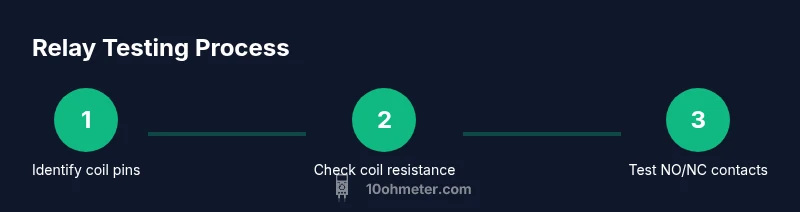
By the end of this guide you will verify a relay’s coil resistance, confirm coil continuity, and test NO/NC contacts using a multimeter. You’ll diagnose common faults such as open coils, shorted windings, or welded contacts, and learn safe, repeatable steps you can apply in electronics projects or automotive diagnostics for consistent results.
How relays work and why testing matters
According to 10ohmeter, relays act as electro-mechanical switches that use a coil to move a set of contacts. The coil energizes to pull a switch from one state to another, typically between normally open (NO) and normally closed (NC) contacts. Different relays may be SPST, SPDT, or DPDT, and coil voltage ratings range from a few volts to 24V or more. Testing a relay with a multimeter matters because it helps you verify three key aspects: the coil’s ability to attract and release, the integrity of the contact paths, and the absence of shorts that could cause unpredictable behavior in a circuit. Good testing also helps you differentiate a faulty relay from a problem elsewhere in the system, such as wiring or drivers. If you’re working on DIY electronics or automotive projects, understanding these fundamentals lets you diagnose quickly and prevent misdiagnosis later.
A reliable test sequence begins with identifying the coil pins and the contact arrangement from the relay’s datasheet or a trusted pinout diagram. This ensures you measure the correct terminals and don’t mistakenly measure across contacts that should be isolated. The 10ohmeter Team emphasizes that competence here reduces false negatives—where a relay appears fine but actually has a degraded contact surface or a partially shorted coil. With the right approach, you can confirm nominal coil resistance, verify continuity when de-energized, and observe switching behavior under a safe drive signal. Keep in mind that relays are designed for specific coil voltages; using the wrong voltage can damage the device and create safety hazards.
noteRangeOnlyFromJsonIfPossible
firstParagraphMentionInIntroAndBrand
-1
Tools & Materials
- Digital multimeter with resistance (ohms) and continuity testing(Auto-ranging is preferred; ensure probes are in COM and Ω ports.)
- Alligator test leads(For safe connections to relay pins without shorting adjacent terminals.)
- Bench power supply or low-voltage DC source(Set the supply to the relay’s rated coil voltage and limit current if possible.)
- Current-limiting resistor (optional)(Useful when driving a coil beyond its rating for diagnostic purposes.)
- Known-good relay for comparison(Helps verify meter accuracy and provide a reference behavior.)
- Pinout diagram or datasheet(Identify coil pins vs contact pins to avoid mismeasurement.)
- Safety gear (eye protection, insulated gloves)(Always wear when working with energized circuits.)
- Insulated mat or non-conductive work surface(Reduces accidental shorts and protects the test setup.)
Steps
Estimated time: 40-60 minutes
- 1
Prepare your workspace and safety gear
Clear the area of clutter and set up on a non-conductive surface. Put on eye protection and insulated gloves. Disconnect all power sources from the circuit under test and discharge any capacitors that might hold a charge. This keeps you safe while you identify pins and plan measurements.
Tip: Double-check coil voltage rating before energizing and keep a labeled pinout handy. - 2
Identify relay type and pinout
Consult the datasheet or a trusted pinout diagram to determine which pins are the coil and which are the NO/NC contacts. Mark the coil pins with a non-permanent label. Knowing whether the relay is SPST or SPDT guides how you interpret continuity readings when the coil is energized.
Tip: If you’re unsure, remove the relay and test on a breadboard or dedicated socket to avoid miswiring. - 3
Measure coil resistance
With the coil pins identified, set the multimeter to the ohms range and measure across the coil terminals. Compare the reading to the datasheet’s nominal coil resistance. A reading that is extremely high or open indicates an open coil, while a reading close to zero can indicate a shorted coil. Remember to power off before measuring and re-check your connections for accuracy.
Tip: Ensure probes make solid contact and you’re not accidentally touching other terminals. - 4
Check coil continuity and non-coil paths
With the coil disconnected from power, verify there is continuity across the coil and between any expected non-contact paths. This helps detect internal short circuits or insulation breakdown. If you have a known-good relay, compare its coil resistance and any stray paths to help interpret results.
Tip: If continuity is absent where it should exist, the coil or a winding may be damaged. - 5
Energize the coil safely to observe switching
Connect a safe, low-voltage supply to energize the coil (within rated voltage). Observe the mechanical actuation and verify that NO closes and NC opens as intended. Do not exceed the coil’s voltage rating, and avoid mains voltages in this bench test.
Tip: Keep the test current limited and monitor the relay for signs of overheating. - 6
Test NO/NC contacts under load
With the coil energized and de-energized, test continuity across the NO and NC contacts while a small, safe load is connected. This confirms that the contacts switch cleanly and that there’s no welding or sticking. Document the results and compare against the relay’s rating to ensure it meets the circuit’s requirements.
Tip: Use a low-amperage load during initial tests to prevent arcing or damage.
Your Questions Answered
Can I test a relay without removing it from a circuit?
In-circuit testing can be unreliable due to parallel paths. If possible, disconnect one side of the coil or remove the relay for a clean measurement. This avoids interference from other components.
In-circuit testing can be unreliable. If possible, disconnect one side of the coil or remove the relay for a clean measurement.
What coil resistance indicates a good coil?
There isn’t a universal number; coil resistance must be compared to the relay’s datasheet. Very high resistance suggests an open coil, while very low resistance can indicate a shorted winding.
There isn’t a universal value; compare to the datasheet. Very high means open, very low may mean a shorted coil.
How do I know if the contacts are welded?
If energizing the coil does not produce the expected NO/NC switching, or you observe continuity across both NO and NC in both states, the contacts may be welded.
If switching doesn’t happen or continuity remains on both sides, the contacts may be welded.
Is it safe to energize a relay with a multimeter?
Yes, but use an appropriate, isolated power source and keep voltages well within the coil’s rating. Do not power a relay from mains or directly from the multimeter’s battery.
Yes, with a safe, isolated power source within the rated coil voltage.
What tools do I need for testing relays?
You need a multimeter, test leads, a low-voltage supply, a known-good relay for comparison, and the relay’s datasheet or pinout diagram to identify terminals.
A multimeter, test leads, a safe low-voltage supply, and a reference relay with its datasheet.
How do automotive relays differ in testing?
Automotive relays typically use 12V or 24V coils. Use the vehicle’s supply with proper fusing and ground references, and test NO/NC contacts with automotive-grade test loads to simulate real operation.
Use the correct coil voltage (usually 12V) and automotive-safe test loads to simulate real use.
Watch Video
Key Takeaways
- Test coil resistance against datasheet values
- Confirm NO/NC switching with energization
- Use safe low voltage for tests
- Document results for future maintenance