How to Find Ground Fault with a Multimeter: A Practical Troubleshooting Guide
Urgent, practical guide to locating ground faults with a multimeter. Learn safe steps, diagnostic flow, and prevention tips to protect people and equipment from shock and fires.

Ground faults pose shock and fire risks, so the quickest path to safety is to power down the circuit, unplug devices, and verify absence of voltage. The most likely fault path is insulation leakage or a miswired ground. Use a multimeter to check continuity, resistance, and grounding paths, isolating sections to locate the fault quickly.
What is a ground fault and why it matters when testing with a multimeter
A ground fault occurs when current finds an unintended path to the earth or chassis ground. When you test or service circuits, understanding how to find ground fault with multimeter is essential to prevent electric shock, equipment damage, and nuisance tripping. Ground faults can appear in outlets, appliances, or wiring branches and are more common when insulation is worn or moisture is present. In practical terms, you look for an unwanted leakage current path and verify that the grounding conductor is continuous and properly bonded. By systematically testing with a multimeter, DIY enthusiasts and technicians can locate the fault without guessing, reducing downtime and risk. Remember: quality testing hinges on safe, deliberate steps, not speed.
Safety first: preparing your workspace and multimeter
Before you touch any live circuit, establish a safe working area. Wear insulated gloves if available, stand on a non-conductive mat, and keep one hand in your pocket to minimize shock risk. Inspect your multimeter for proper leads, intact insulation, and the correct settings. Use a meter with a dedicated ground reference and a test lead rated for the voltage you’re measuring. Keep a clear line of sight to the circuit breaker panel, and always turn off the power at the source before making measurements on exposed conductors. If you must measure live circuits, use non-contact voltage testers first to confirm power is off, then proceed with caution.
Quick checks before tracing the fault
Start with a visual inspection: look for damaged insulation, frayed wires, and corroded outlets. Check that the grounding conductor is connected to the metal box and to the earth ground rod (where applicable). Use your meter to verify continuity between the ground pin, the metal box, and the equipment chassis. A dead grounding path usually shows very low resistance; any unexpected readings suggest a broken or loose ground. If you find a grounding mismatch, isolate the suspect section and tag it for repair. Document every step as you go to avoid re-work.
Diagnostic flow: a structured approach to locating the fault
A logical sequence helps you identify the fault efficiently. Start by powering down and isolating the circuit. Test for continuity between chassis ground and earth ground; a healthy system should show clear continuity. Next, measure insulation resistance between live conductors and ground; a fault usually reduces insulation resistance. If readings are inconclusive, progressively disconnect downstream devices and re-test. Use a combination of voltage checks, continuity tests, and insulation resistance tests to triangulate the leak path. If at any point you suspect mains voltage or high risk, stop and call a professional.
Step-by-step: isolating and fixing the fault
- power down, unplug, and verify no voltage; 2) identify all likely ground paths (outlets, appliances, metal boxes); 3) test continuity between ground and metal parts; 4) check insulation resistance from hot to ground; 5) isolate sections by removing devices or outlets one at a time; 6) repair damaged insulation or replace faulty components; 7) re-test all paths and re-energize the circuit only after confirming safe readings.
Tip: Keep each measurement labeled and re-check dubious connections after repairs.
Prevention, tests, and maintenance to avoid future ground faults
Regular inspection of outlets, cords, and appliances for wear helps prevent ground faults. Use a dedicated outlet tester periodically to confirm proper grounding, and perform insulation resistance tests after any major repair. Consider upgrading old branch circuits and ensuring that all metal enclosures are properly bonded. Maintain a maintenance log for electrical components and replace damaged cables promptly. By building a habit of proactive testing, you reduce the risk of shocks and circuit damage over time.
Final verification and safe restart
After repairing, re-check every path from the grounding conductor to exposed metal parts and ensure insulation resistance readings meet manufacturer specs. Confirm no voltage appears on chassis when the circuit is energized under normal load. If the readings remain within acceptable ranges and the grounding path is solid, you can safely restore power. If any doubt remains, pause and seek a qualified electrician.
Automotive circuits: special considerations
Ground faults in automotive wiring can be harder to trace due to transient loads and battery grounding schemes. Use the multimeter to verify continuity between chassis ground and the battery negative, then test insulation resistance on high‑current harness sections. Isolate sections by removing fuses or disconnecting modules, and test with the engine off and key out of the ignition to minimize risk. Always wear eye protection and keep the vehicle on a dry surface when performing checks.
Steps
Estimated time: 40-90 minutes
- 1
Power down and secure the area
Turn off the breaker, unplug devices, and switch off the main power if required. Verify with a non-contact tester that the circuit is de-energized.
Tip: Use one hand in your pocket to reduce shock risk. - 2
Set up your meter and tools
Gather a digital multimeter with solid insulation leads, a non-contact tester, and a clean workspace. Confirm the meter is on the correct setting for continuity and insulation resistance.
Tip: Check the meter’s probes for wear before use. - 3
Check grounding path visually
Inspect outlets, metal boxes, and exposed conductors for visible damage. Ensure the grounding conductor is connected to the earth ground and to the chassis where applicable.
Tip: Look for loose screws or corroded connectors. - 4
Test continuity and bonding
With the circuit still de-energized, measure continuity between ground pins and metal parts. A healthy path should show low resistance.
Tip: Document any unexpected readings with a photo for later repair. - 5
Measure insulation resistance
Test between live conductors and ground to check for leakage. Pay attention to readings that drift under load or after cooling.
Tip: Follow manufacturer guidelines for insulation test voltage. - 6
Isolate and repair
If a specific outlet or segment tests weak, disconnect it and repair or replace wiring, outlets, or devices as needed.
Tip: Only proceed to re-energize after all readings are within spec.
Diagnosis: Outlets or devices show a potential shock risk, tripped breakers, or unexpected voltage on ground.
Possible Causes
- highDamaged insulation or exposed conductors causing current to leak to ground
- mediumNeutral-ground bonding in appliances or panels miswired
- lowMoisture ingress or corroded wiring creating leakage paths
Fixes
- easyPower down and unplug the circuit; verify no voltage with a meter
- easyIsolate sections by removing devices/outlets and test continuity between ground and chassis
- hardRepair insulation, replace damaged cables, and correct grounding connections
Your Questions Answered
What tools do I need to find a ground fault with a multimeter?
Essential tools include a digital multimeter capable of continuity and insulation resistance testing, proper test leads, and a non-contact voltage tester for safe power checks. Having gloves and eye protection is also advisable.
You’ll need a good multimeter, test leads, and a non-contact tester to safely check for ground faults. Don’t skip safety gear.
Can I test ground faults in live circuits?
Testing live circuits increases risk. If you must, use non-contact testing first, then proceed with extreme caution and proper PPE. Prefer de-energizing the circuit whenever possible.
Live testing should be avoided if you can de-energize the circuit. Use non-contact checks first.
How do I differentiate a ground fault from a loose connection?
A ground fault typically shows leakage current to earth with reduced insulation resistance, while a loose connection often presents as intermittent voltage or heat alongside normal insulation readings. Use a systematic approach to verify both possibilities.
Look for leakage to ground with insulation resistance drops to tell between faulty insulation and a loose connection.
What if the fault is in the main panel?
If you suspect the main panel, avoid complex probing and contact a licensed electrician. Faults in the panel can pose serious shock and fire hazards.
Panel faults are risky; if suspected, call a professional for safety.
How often should I verify grounding in a home?
Regular checks every 1–2 years, or after major electrical work or weather events, help ensure safe grounding paths and identify aging components early.
Do grounding checks every couple of years or after big electrical work.
Watch Video
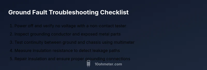
Key Takeaways
- Start with safety and isolation before testing.
- Use continuity, resistance, and insulation tests to locate leaks.
- Systematically isolate sections to pinpoint the fault.
- Repair damaged insulation and confirm grounding paths.
- Document findings and verify with a final check before restoring power.