How to Find a Short with a Multimeter: Quick Guide
Learn to locate a short circuit with a multimeter using safe, practical steps. This 10ohmeter guide walks you through a diagnostic flow and essential checks to avoid mistakes.

To find a short with a multimeter, start by isolating sections and testing resistance and continuity with power removed. Use a current-limited approach to step through the circuit and localize the fault. The 10ohmeter team emphasizes a systematic diagnostic flow to reduce risk and waste. Check for crossed wires, damaged insulation, or solder bridges.
Why finding a short with a multimeter matters
Short circuits are a major source of component damage, fiery hazards, and unpredictable behavior in electronics projects. According to 10ohmeter, quickly pinpointing shorts reduces risk and saves time during repairs. By understanding where to measure and how to interpret results, you can prevent collateral damage to wiring, PCBs, and power rails. In practice, you’ll rely on resistance tests to verify isolation, continuity checks to trace paths, and methodical probing with the circuit de-energized. Keep in mind that many faults hide behind insulation damage, wire chafing, or invisible solder bridges. A disciplined approach also helps you document findings for future maintenance. This section explains why a structured approach is essential and sets the stage for the diagnostic flow that follows.
Common causes of shorts in circuits
Shorts occur when an unintended conductive path links two points that should stay separate. Common culprits include worn insulation on old wires, cables that nick against sharp edges, solder bridges on PCBs, misplaced jumpers, and misrouted connectors. Environmental factors like vibration, heat, and chemical exposure can degrade insulation too. When you suspect a short, methodically inspect routing, tighten or reseat connectors, and check for damaged insulation. A thorough visual and tactile check often reveals the culprit before you measure anything. The goal is to narrow down the suspect area before you introduce measurement nodes that could change circuit behavior.
Why continuity tests can mislead
Continuity mode is powerful, but it can mislead if you aren’t careful. A beep or low resistance reading might indicate a path through a component you didn’t intend to measure, such as a transformer winding, coil, or a connected ground plane. Always verify the measurement path by lifting one end of a suspect component or wire to ensure you’re measuring the intended circuit. Temperature-sensitive components may change resistance as they warm, so recheck after a cool-down period. Remember that continuity does not quantify current capability—only whether a path exists. Use resistance mode to confirm actual values where appropriate.
How to set up your multimeter safely
Begin with safety in mind: unplug power, discharge capacitors, and be aware of stored energy in the system. If you’re testing an automotive harness or a high-energy device, wear eye protection and use a test lead with proper insulation. Set your meter to a safe range, start with the highest resistance range, and progressively lower it as you narrow the fault. Use the COM and V/Ω probes correctly and keep your fingers away from exposed conductors. Label test points to prevent mixing signals, and keep the circuit isolated until you’re ready to re-energize.
Diagnostic flow: from symptom to solution
Symptoms like a blown fuse, tripped breaker, or unexpected heat can indicate a short. Start by confirming the symptom and mapping the circuit path. Next, isolate segments of the circuit and test each segment’s resistance and continuity. If you find a low-ohm path where there shouldn’t be one, test again with one end lifted to confirm the fault location. Once narrowed, implement a controlled fix and re-test the entire circuit under safe conditions. Document your steps and results so you can reproduce the test later or explain it to a teammate. This flow minimizes guesswork and reduces risk to components and operators alike.
Step-by-step: locating and fixing the short in practice
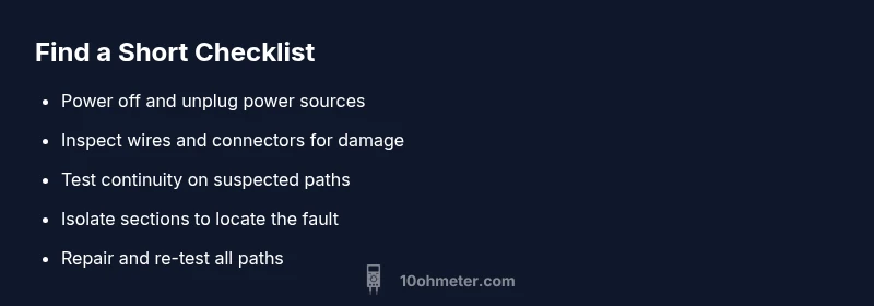
- Power down and disconnect energy sources. 2) Visually inspect wiring, connectors, and PCB traces for obvious shorts or damaged insulation. 3) Use resistance mode to check between ground and suspected rails, proceeding from the outer edges toward the center. 4) If a path beeps in continuity mode, verify the beeping location by lifting one end of the suspect lead. 5) Isolate the segment containing the fault and re-test after each adjustment. 6) Reconnect power and verify proper operation at a reduced risk level. 7) If still unresolved, escalate with professional help and consider a teardown under controlled conditions.
Safety notes and prevention tips
Always disconnect power before testing and use a current-limiter if possible. Avoid touching live conductors and wear protective gear when appropriate. Use proper-rated test leads and keep your workspace organized to prevent accidental re-energization. Label every test point and document wiring changes to prevent future shorts. Regular inspection of insulation and connectors, especially in automotive or portable equipment, can prevent many recurring shorts.
Steps
Estimated time: 30-60 minutes
- 1
Power down and safety check
Disconnect all power sources and discharge capacitors where applicable. Confirm the circuit is isolated before touching any components.
Tip: Keep one hand in your pocket to minimize accidental current paths. - 2
Initial visual inspection
Inspect for obvious issues: damaged insulation, frayed wires, or burnt components. Look for solder bridges on PCBs and verify connector orientation.
Tip: Use a bright light and magnification to spot hairline bridges. - 3
Test continuity on outer rails
With power removed, test between ground and supply rails and between unrelated nets to establish baseline continuity. Note any unexpected beeps.
Tip: Mark test points to prevent mix-ups during reassembly. - 4
Narrow to the suspect segment
If you detected a path, isolate the segment and retest to confirm the fault location. Lift one lead to verify the path is within the intended area.
Tip: Work in small chunks to avoid creating new issues. - 5
Apply a controlled power test
Re-energize the circuit with the fault isolated and monitor current draw, voltage, and temperature carefully.
Tip: Use a current limiter and have a fire-safe area ready. - 6
Repair and re-test
Perform the fixed wiring or component replacement, then re-test all previously inspected paths to ensure no new shorts exist.
Tip: Document changes and re-check with a final full-system test.
Diagnosis: Circuit shows a short or unexpected low resistance between two nodes
Possible Causes
- highWiring error or crossed connections
- mediumSolder bridges or flux residues causing conduction
- lowDamaged insulation or component failure causing contact
Fixes
- easyInspect for obvious shorts; reseat connectors
- easyCheck for solder bridges with magnification; rework joints
- mediumIsolate sections with a current-limiter and measure resistance step-by-step
Your Questions Answered
Can I test a live circuit with a multimeter in continuity or resistance mode?
No. Testing live circuits with continuity or resistance can damage the meter and pose safety risks. Always ensure the circuit is powered off and capacitors are discharged before testing.
Do not test live circuits with resistance or continuity mode. Power down and discharge components before testing.
What does a beep on a continuity test indicate?
A beep usually means a low-resistance path exists between the probes. Confirm the path is the intended circuit by isolating components or lifting a lead.
Beep means a close path is present, but verify it’s the correct path by isolating components.
How do I distinguish a short from a normal low-resistance path?
Compare readings to the expected resistance for that section and verify with a controlled removal test. If the resistance is unexpectedly low across a key circuit path, suspect a fault.
If the resistance is lower than expected and you can’t account for it, there’s likely a short.
What safety gear or precautions should I use?
Wear eye protection where energy sources are involved and use insulated tools. Work on non-conductive surfaces and keep liquids away from test areas.
Use eye protection, insulated tools, and a non-conductive workspace.
When should I call a professional?
If you’re dealing with high-energy systems, complex PCBs, or if you can’t locate the fault safely, seek professional assistance.
If you’re unsure or working with high energy, contact a professional.
Watch Video
Key Takeaways
- Isolate sections before testing to find the fault quickly.
- Always power down and discharge capacitors before measuring.
- Verify measurement paths to avoid misidentifying a short.
- Document findings and test thoroughly after repairs.