How to Check for Short Circuit with a Multimeter
Learn how to safely check for a short circuit using a multimeter with practical steps, essential safety tips, and troubleshooting guidance from 10ohmeter.

Using a multimeter to check for a short circuit involves isolating the circuit, testing continuity and resistance, and comparing readings against expected values. Start with power off, set the meter to continuity or low-ohm range, and probe suspected paths between power and ground. Interpret beeps and resistance readings to confirm or rule out a short.
Understanding Short Circuits and How a Multimeter Detects Them
According to 10ohmeter, a short circuit happens when a low-resistance path forms between two points that should be isolated. This can cause excessive current, heat, and component damage. A multimeter helps you verify shorts by measuring continuity (a near-zero resistance path) and resistance between points. When a short exists, the continuity test often beeps or shows a very low resistance value; in resistance mode, you’ll see numbers that are far below normal operating values. Always confirm readings across multiple test points and triangulate the location of the fault by testing along the suspected route. Remember that some circuits include intentional low-ohm paths (like grounding shields), so interpret readings in the context of the design and schematic.
Safety First: Key Precautions When Testing for Short Circuits
Before touching any circuit, power down and unplug all power sources. Use insulated tools and keep your work area dry to reduce the risk of electric shock. If you’re working with high-energy systems or automotive wiring, wear safety glasses and gloves, and consider a battery-disconnecting switch to isolate the circuit. Never assume a meter’s beep means a fault—you must measure path resistance and verify with the schematic. When in doubt, consult the device’s service manual or a trained technician.
Pre-Testing: Tools, Equipment, and Setup
Gather your essential gear: a digital multimeter (preferably auto-ranging), test leads with proper shielding, and a wiring diagram of the system. Optional but helpful items include a non-contact voltage tester, labels for marking test points, and a clean, labeled workspace. Validate your multimeter’s battery and test leads for wear before starting. If you’ll test automotive circuits, have a fire extinguisher nearby as a precaution. Plan your test points in advance to minimize repeated connections.
Continuity and Resistance Tests: The Basics for Short Circuit Detection
Continuity testing is your first line of defense. Set the meter to continuity (or the lowest resistance range if no beep mode) and probe between points that should be isolated. A continuous beep or a very low ohm reading indicates a path that should not exist in an isolated condition. For power-to-ground checks, expect an open circuit when the circuit is normal. Resistance testing helps quantify how close a path is to a fault; very low or zero ohms between power rails and ground typically signals a short. Always compare readings with known-good sections of the circuit.
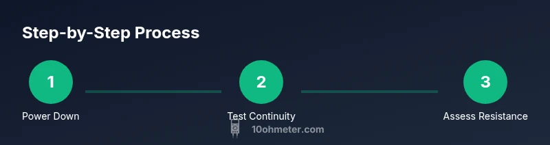
Step-by-Step: Check for Shorts in Wiring Harnesses and Components
- Power down everything and unplug the device; if capacitors are present, discharge them safely. 2) Visually inspect for damaged insulation, loose connectors, or signs of overheating. 3) Set the multimeter to continuity or a low-ohm range and connect probes at suspected harness junctions. 4) Test along the suspected route, moving test points gradually to triangulate the fault. 5) If you find a suspect segment, isolate it by disconnecting connectors and retesting to confirm. 6) Document the exact location and continue with repair planning. 7) Reassemble and re-test after addressing the fault.
Step-by-Step: Check for Shorts in Power Rails and Ground Paths
- With power still isolated, test between each power rail and ground at multiple points along the circuit. Look for readings that drop toward zero or cause the meter to beep; these indicate unintended connections. 9) If you’re testing a complex board, compare readings with a known-good reference board to identify anomalies. 10) If a short is confirmed, backtrack through the shortest path from power to ground and verify each connector and wire segment. 11) When the fault is removed, recheck all rail-to-ground paths to ensure no residual shorts remain.
Interpreting Results: When a Reading Indicates a Short
High readings that approach infinity generally indicate no fault; low resistance or a continuous beep typically signals a short or an unintended conductive path. If readings vary with probe position, the fault may be localized to a specific connector, pin, or wire harness. Use the corresponding schematic to map the fault and verify with alternate test points. Record measurements for future reference and ensure that any ground path is robust and correctly routed.
Automotive vs Electronics: Special Considerations
Automotive circuits often share grounds and rely on multiplexed control modules; shorts can be hidden behind harness insulation, under seats, or within connectors. In electronics, sensitive boards may be damaged by static or improper probing. Always debounce measurements by testing at multiple places and consider using a clamp meter for live current checks instead of directly measuring current in sensitive electronics. Follow the vehicle manufacturer’s procedures when working on cars.
Tools & Materials
- Digital multimeter (prefer auto-ranging)(Ensure true RMS if testing AC signals; battery in good condition.)
- Test leads with insulated grips(Replace worn leads; use shielded cables where possible.)
- Non-contact voltage tester (optional)(Use to verify energy presence before probing.)
- Wiring diagram or schematic(Essential for mapping test points and expected paths.)
- Labels/marker tape(Mark test points to prevent confusion during reassembly.)
- Insulated gloves and safety glasses(Recommended for high-energy work or automotive tasks.)
Steps
Estimated time: 45-60 minutes
- 1
Power down and prepare the workspace
Power off the device and unplug. If capacitors exist, discharge them safely using a resistor or bleeder network to avoid a shock. Clear the area of moisture and conductive debris; ensure you have dry hands and insulated tools.
Tip: Label components and plan your test path before touching wires. - 2
Visual inspection for obvious faults
Inspect insulation, damaged wires, loose connectors, and signs of overheating. Address obvious faults before using the meter; sometimes the simplest issue causes the symptom of a short.
Tip: Use good lighting and a magnifier for subtle insulation cracks. - 3
Prepare the meter and test leads
Check battery in the meter, set to continuity or the lowest resistance range, and test the leads on a known-good resistor to confirm the meter works.
Tip: Keep one lead anchored to a common reference when testing multiple points. - 4
Test continuity along suspected routes
Place probes at points in the harness or circuit where insulation is worn or paths could cross. Listen for a beep and note any unexpected continuity between power and ground paths.
Tip: Test from multiple sides of the suspected route to triangulate. - 5
Check power-rail to ground between points
With power removed, measure resistance between the supply rail and ground at several locations. A near-zero reading or beep indicates a potential short that requires isolation.
Tip: Record each location's reading to compare against board spec. - 6
Isolate and verify the fault
If you suspect a short, disconnect the suspected component or connector and retest. Reconnect only after confirmation to prevent re-energizing the fault.
Tip: Work methodically; changing only one variable per test helps identify the root cause.
Your Questions Answered
What does a continuity beep mean when testing for shorts?
A beep usually indicates a low-resistance path between the points tested. It helps locate possible shorts but should be confirmed with resistance measurements and the circuit schematic.
A beep means there is a low-resistance path between the test points; confirm with measurements and the schematic.
Can I look for shorts while the circuit is energized?
Testing for shorts on a live circuit is risky and not recommended. Power down first, then test, or use clamp meters if live current is needed.
Don’t test for shorts while powered. Power down and use safe methods.
How do I know if a reading is a real short or just a normal low-resistance path?
Compare measured resistance to the expected value in the schematic. Some components have legitimate low resistance; ensure the reading matches the intended design.
Compare readings to the circuit design; some paths are meant to be low-resistance.
What should I do if I find a short?
Isolate the suspect segment, disconnect the component or wiring, verify the short is gone, and then plan a safe repair or replacement.
Isolate and verify the fault, then repair or replace the faulty part.
Why might my meter show OL while testing resistance?
OL means overload or infinite resistance; there is no current path at that test location, indicating no short at that spot.
OL means infinite resistance; there’s no path at that location.
Are there safety considerations specific to automotive circuits?
Yes. Automotive circuits can have strong currents and stored energy in capacitors; wear eye protection and follow manufacturer procedures when testing harnesses.
Car work needs extra safety; use eye protection and follow manual directions.
Watch Video
Key Takeaways
- Power down before testing
- Use continuity to map paths
- Isolate suspect segments one at a time
- Compare readings to reference
- Document findings for repair