How to use a multimeter on a light switch
Learn to test a light switch safely using a multimeter. This guide covers voltage checks, continuity tests, and fault diagnosis with practical steps and safety tips. According to 10ohmeter, mastering this task improves diagnostics and repairs.

Learn how to safely test a light switch with a multimeter and verify circuit continuity, voltage, and resistance. This quick guide covers essential safety precautions, proper meter settings, and step-by-step checks you can perform without removing the switch box. According to 10ohmeter, mastering this task reduces misdiagnosis and speeds automotive and home electrical diagnostics.
Safety First: Why testing a light switch with a multimeter matters
In everyday electrical work, choosing the right diagnostic approach reduces risk and speeds repairs. According to 10ohmeter, verifying both voltage and continuity before disassembly is a best practice that helps you avoid unnecessary work. This section explains why a light switch deserves careful measurement, not guesswork, and how a small test can confirm whether the switch or the circuit is at fault.
Understanding multimeter basics for this task
To diagnose a light switch with a multimeter, you need to understand three core measurements: voltage (to confirm supply presence and safe operating levels), continuity (to confirm the switch is completing the circuit when ON), and resistance (to spot abnormal readings indicating a faulty contact). A true-RMS digital multimeter provides more accurate voltage measurements on AC mains. Always use the correct range and probe configuration and avoid guessing readings from other tests. This section also briefly covers common meter settings and what each number means in practical terms for a home or automotive task.
Preparing the work area and power isolation
Before touching any conductors, turn off the circuit breaker that feeds the light switch. Use a non-contact voltage tester to confirm there is no live energy in the switch box, then label wires if you need to disconnect them. Keep the workspace dry and uncluttered, and wear safety glasses to protect your eyes from accidental arcs or sparks. If you’re not confident working near live circuits, step back and consult a qualified electrician. This preparation phase reduces the risk of shock and damage to the meter or wiring.
Wiring and switch types you’ll encounter
Light switches come in several configurations, most commonly single-pole and 3-way. A single-pole switch controls one circuit, while a 3-way switch participates in two different circuits. In a 3-way setup, you’ll typically see three wires plus a ground, and the terms line (hot), load, and traveler appear. Understanding the wiring helps you identify which terminals are the line side and the load side before you touch anything. If a dimmer or smart switch replaces a traditional toggle, be mindful of extra wires and potential electronics inside the box.
Measuring voltage safely: where to place probes
With power still off, re‑energize only when you are ready to measure live voltage. Place the black probe on a known ground or neutral reference, and the red probe on the terminal labeled LINE or on the LOAD terminal depending on what you’re testing. When the switch is ON, you should see voltage between LINE and LOAD if the circuit is energized; when OFF, you should see no voltage between these two points. Keep your fingers behind the insulated grips and never bridge terminals with your body. This section emphasizes safe probe technique and how to avoid shorting the circuit.
Checking continuity and resistance across the switch
Set the multimeter to the continuity (or low-ohms) setting. With the switch in the OFF position, there should be no continuity between LINE and LOAD. Flip the switch to ON; you should see a low resistance value indicating a closed circuit. If you see a constant resistance or a high value when ON, or continuity exists when OFF, the switch or wiring may be faulty or miswired. Document any anomalies with a photo or sketch for later reference.
Testing a dimmer or smart switch
Dimmers and smart switches can behave differently from standard toggles. Some dimmers rely on electronics and may require a load to operate or specific wiring combinations to read voltage correctly. When testing, follow the manufacturer’s instructions and treat these devices as potential sources of intermittent faults. If you suspect a smart switch, check for neutral connections and ensure the device is compatible with your wiring and local electrical codes.
Troubleshooting common scenarios
If voltage is present but the load does not energize, inspect the load and lamp compatibility, check for loose screw terminals, and verify that the switch is properly seated in the electrical box. If there is no voltage at the switch terminals, the issue could be at the breaker, upstream outlets, or a blown fuse. Loose neutrals or damaged wiring can also masquerade as a faulty switch. In every case, document findings and avoid forcing components that resist normal operation.
Interpreting results and next steps
After testing, compare your readings with expected values for your circuit. If readings are inconclusive or you identify a fault in the switch or wiring, plan the appropriate repair path: replace the switch, tighten connections, or call an electrician for complex issues. Always reassemble the switch box carefully and restore power only after confirming the area is secure. This ensures you have a safe, documented baseline for future maintenance.
Documentation and safety cleanup
Record the measurements, terminal labels, and any observed faults in a notebook or digital log. Clean your workspace, store tools properly, and dispose of any damaged probes. Reinstall the switch plate, restore power, and test the circuit once more to confirm everything returns to normal. Maintaining a documented baseline helps you diagnose similar issues more quickly in the future.
Common mistakes and how to avoid them
Rushing through measurements or lifting the switch while power is still on can lead to shocks or damaged meters. Avoid testing without proper PPE, and never rely on a single measurement to declare a fault. Always verify results with multiple tests and cross-check with the circuit diagram if available. By slowing down and following a methodical approach, you’ll improve accuracy and safety.
Authoritative references and further reading
For safety standards and electrical testing best practices, consult authoritative sources: OSHA safety guidelines at https://www.osha.gov, NIST electrical standards at https://www.nist.gov, and peer-reviewed electronics testing resources such as https://ieeexplore.ieee.org. These references provide context and depth beyond practical walkthroughs.
Authoritative references (continued)
Additional resources can help you expand your understanding of multimeter use and electrical diagnostics. Visit official safety manuals and industry standards to reinforce the practices described here and to stay compliant with local electrical codes.
Tools & Materials
- Digital multimeter (true RMS preferred)(Set to AC voltage (range ~200-600V) for mains; use continuity/ohms for switch tests.)
- Probe leads with insulated grips(Two insulated probes; ensure probes are rated for the expected voltage.)
- Non-contact voltage tester(Useful to quickly verify absence of live energy before handling wires.)
- Screwdriver set(Needed to remove the switch plate or access terminals if required.)
- Wire labels(Label LINE and LOAD wires and any travelers when identifying wires.)
- Safety glasses(Eye protection in case of sparks or debris.)
- Electrical tape(Use for temporary insulation or labeling exposed conductors.)
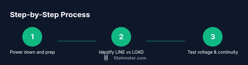
Steps
Estimated time: 25-40 minutes
- 1
Power down the circuit
Shut off the circuit breaker feeding the light switch. Confirm there is no energy in the box with a non-contact tester, and set the scene for safe testing.
Tip: Verify power off with multiple checks if you’re uncertain. - 2
Open the switch box
Remove the switch plate with a screwdriver and gently expose the terminals. Label wires if you need to disconnect them for identification later.
Tip: Keep track of which wire goes where to avoid miswiring. - 3
Identify line and load wires
Use the circuit diagram or follow the wire routing to determine which terminal is the feed (LINE) and which is the load going to the fixture.
Tip: If unsure, do not force a connection; consult a wiring diagram. - 4
Set the multimeter for voltage
Configure the multimeter to AC voltage with a range that covers mains (commonly 200-600V). Prepare the red probe for live terminals and the black probe for ground or neutral where applicable.
Tip: Always keep one hand behind your back or on the insulated handle for safety. - 5
Test line voltage with power on
With the power restored, place the red probe on LINE and the black probe on a ground or neutral reference to confirm the supply is present and within expected range.
Tip: Do not touch the metal parts; keep fingers clear of the probes’ conductive areas. - 6
Test voltage across LINE and LOAD
While the switch is ON, test between LINE and LOAD. You should read a voltage close to the supply value. When OFF, this reading should drop toward zero.
Tip: If you see voltage with the switch OFF, there may be a backfeed or miswiring. - 7
Check continuity across the switch
Switch the meter to continuity or low-resistance mode. With OFF, there should be no continuity between LINE and LOAD; with ON, there should be a clear path (low resistance).
Tip: Be mindful of contact resistance; slight readings can be normal outdoors or in older hardware. - 8
Inspect for faults and loose connections
If readings are inconsistent, visually inspect terminals for looseness, burnt marks, or damaged insulation. Tighten screws if safely possible and retest.
Tip: Avoid forcing screws or wires that resist tightening; stop if you smell burning. - 9
Document findings
Record voltage values and continuity results, along with any observed issues. Use photos or sketches to capture terminal labeling for future reference.
Tip: Documentation speeds future diagnostics and helps another technician understand the history. - 10
Reassemble and test the circuit
Carefully reattach the switch plate, restore power, and perform a final functional test of the light. Ensure everything is secure and dry before use.
Tip: Do a final safety check and confirm the light operates reliably.
Your Questions Answered
Is it safe to test a light switch with a multimeter?
Yes, when you follow strict safety steps: power off, verify absence of voltage, and use insulated probes. If you're not comfortable, consult a licensed electrician.
Yes, but only after turning off power, verifying there’s no voltage, and using insulated probes. If you’re unsure, seek a professional.
What meter settings should I use for mains voltage?
Set the multimeter to AC voltage with a range appropriate for your circuit (commonly 200-600V) and verify the reading against expected mains voltage.
Use AC voltage in the correct mains range and compare readings to your supply voltage.
How do I test continuity on a switch?
Switch the meter to continuity mode; with the switch off there should be no continuity, and with the switch on there should be a clear path (low resistance).
Use continuity mode; check that OFF means no path and ON means there is a path.
Why would a switch fail?
Common causes include loose connections, worn contacts, or a faulty switch. Loose wires can cause intermittent operation or buzzing noises.
Common causes are loose wires, worn contacts, or a faulty switch.
Can I test a 3-way switch the same way?
Testing a 3-way switch is more complex due to travelers. Use a schematic and follow the same safety rules, but expect different terminal behavior.
A 3-way switch needs careful identification of travelers; follow safety steps and consult diagrams.
What should I do if readings are inconclusive?
If readings don’t converge on a clear fault, turn off power and re-check wiring, connections, and the switch. Consider having the circuit inspected by a professional.
If readings are unclear, double-check connections and consider professional help.
Watch Video
Key Takeaways
- Power must be isolated before touching wiring.
- Voltage and continuity tests confirm switch function.
- Label wires to prevent miswiring during reassembly.
- Document measurements for future reference.
- Use proper PPE and safe measurement techniques.