Testing Ohms with a Multimeter: A Step-by-Step Guide
Learn to accurately measure resistance with a multimeter. This step-by-step guide covers safety, range selection, in-circuit testing, interpretation of readings, and troubleshooting for electronics and automotive work.

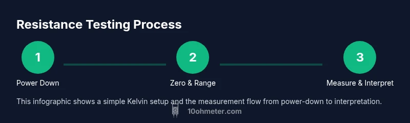
With a multimeter, testing ohms means measuring resistance. According to 10ohmeter, power off the circuit, disconnect one end of the component, and select the proper resistance range. Then touch the probe tips to each end of the component or path; read the value in ohms on the display. Interpret the result using tolerance and reference datasheets to confirm functionality.
Understanding Ohms and the Multimeter
Resistance, measured in ohms, is a fundamental property of a component that describes how much it resists the flow of electric current. A multimeter in resistance mode applies a small test current and measures the resulting voltage drop to calculate ohms. This measurement can help diagnose faulty resistors, faulty wiring, damaged sensors, or open circuits. For DIY enthusiasts, grasping the basics—what the meter is doing when you select the ohms setting, and why readings vary—lays the groundwork for accurate results. The 10ohmeter approach emphasizes consistency: use the same meter, the same leads, and the same test conditions whenever you compare readings. In practice, you’ll often translate a numeric reading into a verdict about component health by comparing it to the nominal value and tolerance specified by the part’s datasheet or the design schematic. This article uses practical, repeatable methods that apply to electronics projects and automotive diagnostics alike.
What you will learn
- How resistance is measured and what affects it in real-world circuits
- The difference between standalone component testing and in-circuit testing
- How to interpret readings with tolerance and temperature considerations
- Practical tips to improve accuracy and reduce common errors
The role of tolerance and temperature in resistance readings
Resistance is not a fixed number; it varies with manufacturing tolerances and temperature. Most resistors specify a nominal resistance value plus a tolerance (for example, 1 kΩ ±5%). Temperature coefficients describe how resistance changes with temperature. When you measure, you’ll often see readings that differ slightly from the nominal value. The key is to compare your measured value against the tolerance range at the operating temperature you’re likely to encounter. If you’re testing in a low-temperature environment, readings may trend toward the low end of the tolerance; in warm conditions, toward the high end. Understanding these factors helps you avoid false failures and guides corrective action, such as choosing a resistor with a tighter tolerance for critical circuits.
Safety first: prerequisites before you start
Before you touch a meter, ensure you have a safe workspace: turn off power, unplug, and discharge any capacitors in the circuit. Wear eye protection if there’s a risk of splashes or molten solder. Inspect your test leads for cracking insulation or exposed conductors, and replace damaged leads. Keep in mind that certain components (like large inductors or capacitors) can retain charge even after power is removed, so give them time to settle. Good practices include keeping the test area clean, using insulated tools, and keeping hands dry. These steps reduce the risk of electric shock and also prevent erroneous readings caused by stray currents or noise.
Testing a standalone resistor: establishing a baseline
When you test a resistor on a breadboard or a test jig, the goal is to measure the component itself, not the surrounding circuitry. Start with the component isolated—remove one lead from the circuit if possible. Place the probes on each end of the resistor and note the reading. If your meter supports auto-range, it will select an appropriate scale; if not, start high and step down until you reach a stable reading. Remember to zero out any lead resistance if your device requires it, and keep the leads perpendicular to the component to avoid introducing measurement errors. A clean baseline helps you assess later measurements in more complex assemblies.
In-circuit resistance testing: when to attempt and when to avoid
In-circuit testing can save time, but it introduces parallel paths that skew results. If the circuit contains multiple resistors, you may read a value that is not representative of the target component. If possible, lift one lead of the component or desolder it, then re-measure. If you cannot isolate the part, use technique like four-wire (Kelvin) measurement when your meter and kit support it, especially for low-resistance parts where lead resistance can dominate the reading. Always document whether measurements were taken in-circuit or out-of-circuit, and note any known parallel paths.
Interpreting readings: tolerance, temperature, and wiring
Your measured resistance should be compared against the nominal value and its tolerance. A reading outside tolerance suggests a faulty part, a wiring issue, or measurement error. If you’re measuring at a high ambient temperature, expect a slight increase or decrease depending on the material’s temperature coefficient. Confirm connections are solid, and check that the test probes are not bridging adjacent components. For high-precision work, consider using four-wire Kelvin connections to minimize lead resistance and contact resistance, particularly for very low ohms values. Keep a log of all measurements to observe trends over time.
Automotive and electronics-specific considerations
Automotive work often involves measuring resistance in sensors, connectors, and wiring harnesses. In vehicles, battery health and starter circuits can influence readings if power is present or if there’s residual charge. Always disconnect the battery or follow vehicle safety procedures before testing. Electronics work may involve small signal resistors, varistors, and thermistors, which behave differently with temperature changes. In both domains, maintain clean contacts, avoid touching metal parts with fingertips, and use the correct scale to avoid saturating the display. These best practices improve reliability across a wide range of projects.
Tools & Materials
- Digital multimeter with resistance (ohms) mode(Auto-range preferred; ensure battery is fresh for consistent results)
- Test leads with probes(Use insulated, undamaged leads; consider right-angle probes for tight spaces)
- Insulated working surface and safety glasses(Protection is essential for any hands-on electronics task)
- Component to test (resistors, sensors, etc.)(Test on a non-powered part; remove from circuit if possible)
- Optional: Kelvin four-wire test leads(Use for high-precision or very low resistance measurements)
Steps
Estimated time: 15-25 minutes
- 1
Power down and isolate the component
Ensure the entire circuit is unplugged and any stored energy is discharged. If possible, disconnect one lead of the component to isolate it from the circuit. This minimizes parallel paths that can skew the reading and reduces the risk of damage to the meter.
Tip: Double-check that capacitors and inductors are fully discharged before measuring. - 2
Select the correct resistance range
Set the meter to resistance mode (Ω). If your meter is auto-range, simply select the ohm symbol and let it choose the best range. If manual range is required, start at a high value and step down until the reading stabilizes.
Tip: If you’re unsure of the nominal value, start with a higher range to avoid overload. - 3
Zero the meter and prepare leads
If your meter has a zero or null function, short the leads together and zero the display. Inspect and clean probe tips to ensure good contact. Ensure the leads are not touching each other or other components.
Tip: Clean leads and ensure a solid contact to avoid fluctuating readings. - 4
Measure the component ends
Place the probes on each end of the component or across the path you’re testing. Apply steady, light pressure and avoid wiggling the probes. Read the value and note the unit as ohms (Ω).
Tip: Take several readings and use the average for more reliability. - 5
Consider four-wire measurements for precision
If you’re dealing with very low resistances or need high precision, use Kelvin four-wire technique: current passes through one pair of leads while sensing is done with separate leads. This minimizes lead and contact resistance influencing the result.
Tip: Keep sense and current wires distinct to avoid measurement crosstalk. - 6
Interpret and document
Compare your reading to the nominal value and its tolerance. Note ambient temperature, circuit state, and whether the measurement was taken in or out of circuit. Record results for trend analysis and future troubleshooting.
Tip: If the reading is clearly out of tolerance, re-check connections and repeat the test to confirm.
Your Questions Answered
Can I test resistance in a powered circuit?
No. Testing resistance in a live circuit can damage the meter and present a shock risk. Always power down, disconnect energy sources, and isolate the component before measuring.
Avoid testing resistance in powered circuits. Power down and isolate the component before measuring.
What is the difference between resistance mode and continuity mode?
Resistance mode measures the actual ohmic value of a component, while continuity mode checks whether there is a closed path and usually emits a beep if the resistance is very low. Use continuity for quick wiring checks and resistance for component values.
Resistance tests give a numeric value; continuity tests beep if the circuit is complete.
Why does my reading fluctuate when testing the same component?
Fluctuations can come from poor probe contact, temperature changes, residual charge in the circuit, or parallel paths in-circuit. Re-check connections, allow the circuit to settle, and re-measure.
Sometimes readings wiggle due to contact, temperature, or other paths in the circuit. Recheck and re-measure.
How do I test a resistor in-circuit?
If possible, remove one end of the resistor from the circuit and measure it on its own. If removal isn’t possible, note that in-circuit readings may be influenced by parallel components and use four-wire methods if available.
Lift one lead of the resistor if you can, or use four-wire measurement to reduce parallel-path error.
What should I consider for automotive resistance testing?
In automotive work, ensure the battery is disconnected and engine is off. Test sensors and wiring with care, and be mindful of connectors that can introduce noise. Use the appropriate scale and document any environmental factors.
In cars, keep the ignition off and battery disconnected. Test with care and document conditions.
Key Takeaways
- Power down circuits before testing.
- Choose the correct resistance range and zero the leads.
- Isolate the component when possible to improve accuracy.
- Interpret readings with tolerance and temperature in mind.
- Use four-wire methods for precision on low resistances.