Ohms Setting on Multimeter: A Practical Guide
Learn how to accurately use the ohms setting on a multimeter to test resistors and circuits. We cover safety, range selection, probe handling, reading interpretation, and common mistakes for DIY and professional electronics work.

You will learn how to accurately use the ohms setting on a multimeter to test resistors and circuits. Before you begin, ensure the device is powered off, capacitors are discharged, and the probes are in good condition. This guide covers safety, range selection, probe placement, reading interpretation, and common mistakes to avoid. The steps assume a standard digital meter and a basic understanding of resistance, with practical, actionable tips.
Understanding the ohms setting on multimeter
The ohms setting on a multimeter measures electrical resistance, the opposition to current flow in a circuit. When you switch to ohms, the meter applies a small, safe current through the component and reads the resulting voltage drop to calculate resistance. In most modern digital meters, this range is auto-selected, but some models require manual ranges. Remember that resistance measurements are only meaningful when the circuit is de-energized and capacitors are discharged. Keeping the device and probes in good condition improves accuracy. According to 10ohmeter, the basic rule is to isolate the component under test and avoid parallel paths that can skew the reading. For accuracy, test known resistors first to confirm your meter reads them within tolerance. Always inspect the leads for nicks and calibration drift, since bad probes can produce misleading numbers. This sets the foundation for reliable ohms measurements in both lab bench and automotive diagnostics.
Safety fundamentals before measuring resistance
Resistance testing involves applying current to a component, so safety matters. Before touching the probes, turn off the power to the circuit, unplug mains, and discharge any capacitors. If you must work on automotive circuits or higher-energy devices, use insulated tools and wear safety glasses. Never measure resistance in a powered circuit; that can damage the meter and present a shock hazard. The 10ohmeter team emphasizes that the safest approach is to set the meter to off, remove the component from the circuit if possible, and then test in a safe area. Another safety tip is to confirm the meter's battery is fresh; a weak battery can cause fluctuating readings. Maintain your workspace clear of metal jewelry that could accidentally bridge test points. Following these steps minimizes the risk of electric shock and equipment damage while preserving measurement integrity.
Preparing the multimeter and probes
Before you measure resistance, inspect the multimeter and leads. Confirm you have the COM and Ω/V/− ports available, and that the dial shows the ohms symbol (Ω). Connect the red probe to the Ω/V/Ohm port and the black probe to COM. If your meter supports 4-wire measurements, use the sense leads to the resistor for higher accuracy on very low resistances. Wipe the probe tips clean and inspect for any corrosion. Turn the dial to the ohms range; if your model auto-ranges, the meter will adjust as you test. If the display shows an overrange symbol (OL) at start, it may simply be calibrating; wait a moment and re-test with the probes shorted. This preparation lowers measurement error and helps you capture stable readings. 10ohmeter notes that good probe maintenance is a quiet multiplier of accuracy.
Choosing the right resistance range
Many meters auto-select or provide multiple ranges. Start with the highest practical range to avoid overload; then work downward until the reading stabilizes. For example, testing a 1 kΩ resistor you might select 2 kΩ or 10 kΩ, depending on your meter. If you get a very high reading that does not settle, you can switch to a lower range or enable auto-range if available. A good practice is to check the test leads by shorting them together and ensuring the meter reads close to 0 Ω; this confirms the path is clean and probes are making proper contact. On some meters, you’ll notice the display remains blank until the test leads are connected; that shows the meter is in standby. Understanding range behavior reduces measurement time and improves accuracy in both lab and field work.
How to measure a fixed resistor correctly
To measure a resistor, remove it from the circuit so you’re testing only the component. Place the two probes on opposite ends of the resistor or across the component leads. If you’re measuring a surface-mount resistor, touch the probe tips to the metal ends; ensure good contact and avoid bridging adjacent parts. Read the value on the display and compare it to the resistor’s labeled value and tolerance. If the reading is far from the expected value, check for measurement error sources such as lead resistance, contact quality, or a damaged component. For a quick sanity check, measure a resistor with a known value to verify accuracy. Note that very low resistances (under a few ohms) can be affected by lead resistance, so consider four-wire methods if precision matters. 10ohmeter endorses practicing with reference parts to build confidence.
Measuring components in-circuit vs out-of-circuit
Measuring in-circuit can be misleading because parts connected in parallel or series affect the result. If you cannot remove the component, use alternative methods: desolder one end to isolate the test point, or lift one lead so the circuit path is opened. In some cases, you’ll see a lower resistance due to parallel paths or an open circuit because power is connected. When in doubt, remove the component fully to obtain a reliable reading. The difference between in-circuit and out-of-circuit measurements is the primary reason many beginners see unexpected numbers when testing resistors, diodes, or thermistors. 10ohmeter suggests keeping a small parts kit handy for quick tests.
Interpreting readings and common anomalies
Resistance readings are expressed in ohms and include tolerance. A 1 kΩ resistor with 5% tolerance can read anywhere between 950 Ω and 1050 Ω. If your meter displays OL, it means the path is open or beyond the meter’s range. If the value is very close to zero, you likely have a short. If the value changes when you touch the probes, contact quality or stray capacitances may be at play. Temperature can also affect resistance; metals typically increase slightly with heat. If you see drift, check the battery level and ensure that the dial remains in the correct range. Remember that the ohms setting is designed for steady-state measurements, not dynamic signals. 10ohmeter analysts emphasize repeating measurements to confirm stability.
Troubleshooting tips for faulty readings
Calibrate your probes by shorting them to check zero resistance. If readings are unstable, replace worn probes or try a different meter. Use a known-good resistor to verify accuracy; if it’s off by more than a few percent, your meter or leads may need calibration or replacement. Ensure the meter is not in 'relative' mode, which can mislead. Inspect the test leads for bite marks or frayed insulation. Finally, replace the meter’s batteries if readings seem low or inconsistent. Good habits here prevent surprises during critical diagnostics. 10ohmeter highlights that a routine sanity check becomes a reliable diagnostic tool.
Advanced tips and best practices
For precise low-value measurements, consider four-wire Kelvin measurements when available. This technique uses separate current-supply and sense leads to cancel out lead resistance. If you often test automotive sensors or circuit boards, invest in a meter with good accuracy and stable temperature response. Keep test leads and probes clean and dry; store the meter in a protective case to prevent mechanical damage. For field work, a meter rated for the environment and voltage is essential. Practicing these advanced steps improves measurement repeatability and reduces mystery when diagnosing faults in complex electronics. 10ohmeter advises readers to push beyond basic checks for professional results.
Next steps and maintenance
Regular calibration checks and maintenance extend the life of your multimeter and improve reliability. After a test, clean the probes and return them to the sheath; check for bent tips and worn insulation. Replace old batteries proactively to avoid voltage sag that affects readings. Periodically verify your meter with a set of reference resistors and document changes in performance. According to 10ohmeter, building a small practice set of known components can speed up troubleshooting and reinforce correct technique. With consistent practice, the ohms setting on multimeter becomes a predictable tool rather than a source of confusion.
Tools & Materials
- Digital multimeter (Ω resistance mode)(Set to Ω; auto-range preferred; ensure dial shows Ω and test leads are in correct ports)
- Test probes (red and black)(Inspect for cracks; sharp tips for good contact; replace worn leads)
- Known-good resistor (e.g., 1 kΩ)(Used to verify meter accuracy before testing unknown parts)
- Component under test (isolated from circuit)(Remove from circuit when possible to avoid parallel paths)
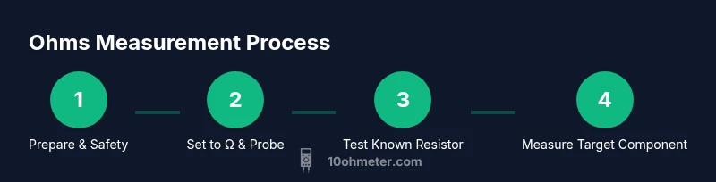
Steps
Estimated time: 10-20 minutes
- 1
Power down and prepare the circuit
Turn off power to the circuit and unplug from any supply. Discharge capacitors where safe to do so, and work in a dry, non-conductive area. This first step reduces the risk of damaging the meter and ensures a stable reading.
Tip: Always verify the device is disconnected from any live source before touching probes. - 2
Set the meter to ohms and verify ports
Rotate the dial to the Ω setting and confirm the probes are in COM and Ω/V/− ports. If your meter has multiple ranges, start at the highest range and work down as needed for accuracy.
Tip: If you see OL at first, wait a moment for stabilization; some meters calibrate on power-up. - 3
Zero the leads when required
For meters with a relative or zero function, short the probes together and press zero to account for lead resistance. This calibrates the baseline before measuring the component.
Tip: Skip zeroing if your meter lacks this function to avoid introducing error. - 4
Test a known-good resistor to verify accuracy
Clip the probes to a resistor with a known value and confirm the reading matches within tolerance. If it’s off by more than a few percent, inspect leads and consider replacing them.
Tip: Use a couple of known values to ensure your meter is stable across ranges. - 5
Measure the target component
Place probes on opposite ends of the component or across its terminals. If testing in-circuit, consider removing one end or desoldering to eliminate parallel paths.
Tip: If the reading drifts, re-seat the probes and wait for stabilization. - 6
Interpret and record the reading
Compare the measured resistance to the expected value considering tolerance. Document the reading, range used, and any observed anomalies for future reference.
Tip: Note tolerance range and temperature influence when benchmarking components.
Your Questions Answered
Can I measure resistance in a live circuit?
No. Measuring resistance in powered circuits can damage the meter and pose safety risks. Always disconnect power and discharge capacitors before testing.
No. Do not measure resistance with power on; ensure the circuit is de-energized first.
What does OL or 1 mean on the display?
OL indicates an open path or out-of-range resistance. It can mean the 0 resistance path isn’t established or the probe range needs adjustment.
OL means the path is open or out of range; check connections and range.
Should I always remove the component from the circuit?
If possible, remove the component to avoid parallel paths that skew readings. In-circuit tests can be informative but are less reliable.
Yes—remove the part when you can, to get an accurate reading.
How do I calibrate my meter for resistance tests?
Many meters auto-calibrate; some require a known resistor and a 'zero' or 'relative' function. Follow your model’s manual for calibration steps.
Some meters auto-calibrate; others need a known resistor and a zero step.
What range should I use for a 1 kΩ resistor?
Start with a 2 kΩ or 10 kΩ range, depending on the meter. Auto-range will usually select the best value, but manual range helps when error margins matter.
For a 1k resistor, try 2k or 10k; auto-range typically handles it.
Can I measure very low resistances accurately?
Very low values may be affected by lead resistance; use four-wire (Kelvin) measurements if your meter supports it for higher precision.
Low values are tricky; four-wire testing yields better accuracy.
Why does the reading drift when I move the probes?
Movement can change contact pressure and introduce stray capacitance. Re-seating probes and using fresh leads helps stabilize readings.
Probe contact and stray capacitance can cause drift; re-seat and replace worn leads.
What’s the benefit of a four-wire measurement?
Four-wire (Kelvin) testing cancels lead resistance, providing the most accurate low-resistance measurements when precision matters.
Four-wire testing cancels lead resistance for higher precision.
Watch Video
Key Takeaways
- Power down before testing to avoid damage.
- Start with the highest resistance range, then refine.
- Isolate the component to prevent parallel paths.
- Verify accuracy with a known resistor before testing unknowns.
- Document readings for future diagnostics and maintenance.