Setting a Multimeter to Ohms: Step-By-Step Guide
Learn how to accurately set your multimeter to ohms to measure resistance, including safety steps, step-by-step methods, and troubleshooting tips for electronics projects.

In this guide you will learn how to set your multimeter to ohms to measure resistance accurately. You’ll need a functioning meter with healthy probes, a known resistor or test component, and awareness of safety cautions. The quick steps, common mistakes, and troubleshooting tips are covered to help you get reliable readings.
Why setting multimeter to ohms matters
Resistance measurement is foundational in electronics troubleshooting and component verification. When you switch a multimeter to the ohms range, you’re asking the meter to quantify the opposition a component presents to current flow. Accurate resistance readings help confirm component values, identify damaged parts, and diagnose circuit faults. The phrase setting multimeter to ohms is more than a label: it signals a deliberate test mode that relies on the meter’s internal reference, probe contact quality, and a stable, isolated test path. In practice, a proper ohms test excludes powered circuits and parallel paths through other components, which can distort results. By mastering ohms measurements, you gain a practical skill that applies to resistors, thermistors, fuses, and even some sensor networks. As you develop consistency, you’ll rely less on guesswork and more on repeatable, verifiable values, which is a core capability for DIY enthusiasts and technicians alike.
Understanding how resistance testing fits into broader electronics work
When you set the meter to ohms, you’re testing how much a circuit resists current under a specific condition. This is governed by Ohm's Law (V = I × R), but for resistance-only readings, you focus on R. Proper technique reduces common error sources such as in-circuit parallel paths, poor contact, or residual charge in capacitors. A good practice is to perform measurements with the circuit unpowered, isolated from other conductive paths, and using clean probe tips. This approach yields more reliable values and helps you interpret tolerance bands on resistors and fixed-value components. Remember that true resistance is a property of the component itself, not a function of the surrounding circuit, so isolating the test subject is essential for accuracy.
The difference between auto-range and manual range in ohms mode
Modern meters offer auto-range for convenience and manual range for precision. Auto-range lets the meter pick a suitable scale, which is handy for quick checks or unknown components. Manual range, however, can provide more stable readings on fixed-value parts or when you’re testing very large or very small resistances. In settings where the result should align with a known value (for example, a 1 kΩ resistor), selecting a narrow range minimizes interpolation errors. If your meter supports both modes, start with auto-range to identify an approximate value, then switch to the closest manual range for stability. This two-step approach reduces fluctuation and improves confidence in the reading.
Safety first: power down, discharge, and proper handling
Always ensure the circuit is powered down before measuring resistance. Residual voltage can damage the meter or cause misleading results. If you’re testing capacitors, discharge them before touching test leads. Handle components with care; avoid twisting leads, which can create noise and contact instability. After power-down, allow any inductive energy to dissipate, then proceed with the ohms measurement. A calm, methodical approach not only protects equipment but also helps you build reliable measurement habits that translate toAutomotive diagnostics and general electronics work.
Getting comfortable with probe contact and test setup
Contact quality matters more than most people realize. Clean probe tips, secure attachment to the component terminals, and minimal lead flex all contribute to stable readings. If a measurement drifts, re-seating the leads and re-zeroing (if your meter includes a zero or relative function) can help stabilize the display. For small or densely-packed components, use a breadboard-friendly jig or a dedicated test fixture to minimize unintended contact. The goal is to create a direct, low-resistance path from the meter probes to the component under test, free from extraneous parallel paths.
How to interpret a stable resistance reading
A stable reading that remains within the expected range indicates the component value is likely intact. Compare your reading to the component’s labeled value and tolerance (for resistors, common tolerances are 1%, 5%, or 10%). If the reading is far outside the expected range, re-check connections, confirm the component is isolated, or consider replacing the part to confirm behavior. When projects require precise tolerances, running a few repeat measurements and averaging can reduce random errors. Consistency is more important than a single precise snapshot.
Special cases: measuring low-ohm components and thermistors
Low-ohm components and thermistors can present challenges because the meter’s own test current affects the reading. In very low resistance ranges, contact resistance and lead resistance become a larger fraction of the measurement, so use the appropriate low-ohm scale and ensure leads are clean. For precision work, remove the device from the circuit and measure across the component leads directly. Be mindful of self-heating at very low resistances, which can slightly alter readings during longer measurements.
Verifying accuracy with a known reference and documentation
To build confidence, validate your meter by measuring a known resistor (e.g., a 1 kΩ part) and compare with its nominal value. Document results, including range, probe condition, and ambient temperature, so you can reproduce measurements later. If discrepancies persist, consider a calibration check or replacement of the meter’s test leads. Regular practice of verifying against reference values improves reliability across all your Ohm measurements and is a foundational habit for electronics work.
Practical tips for everyday projects and repair work
Keep spare test leads and a few reference resistors in your toolkit. Label ranges and remember that meters with auto-range can be very convenient, but manual range offers stability for repeat tests. When troubleshooting, perform measurements at multiple points in a circuit to confirm consistency, and always power down first. By adopting a disciplined approach to setting the meter to ohms, you’ll reduce guesswork and improve your repair quality over time.
Real-world testing scenarios: what to expect in automotive and electronics contexts
In automotive diagnostics, resistance measurements can indicate sensor health, wiring integrity, and component failure. In electronics prototyping, resistance testing helps verify resistor networks and ensure correct circuit behavior. Regardless of context, preparation and isolation are key. A steady, repeatable method makes it easier to isolate problems quickly and avoid misinterpretation caused by in-circuit paths or contact noise.
Conclusion prompts for further practice and learning
Practice with a few test leads, a known reference resistor, and a non-powered circuit until measurements feel routine. As you gain confidence, document your method for future projects, including range choice and any zeroing steps. The more you test and compare, the faster you’ll recognize the expected resistance values for common components and circuits.
Tools & Materials
- Digital multimeter(Set to Ohms (Ω) and use Auto-range if available; verify battery level.)
- Test leads with probes(Inspect for exposed conductors; ensure tips are sharp and clean.)
- Known resistor (e.g., 1 kΩ)(Use to verify meter accuracy and practice range selection.)
- Component under test(Power must be removed and path isolated before measurement.)
- Breadboard or fixture(Optional, helps stable connections for in-circuit tests.)
- Safety gear(Gloves or eye protection as needed for handling exposed circuits.)
- Discharge tool(Optional tool to safely discharge capacitors before measuring.)
Steps
Estimated time: 25-40 minutes
- 1
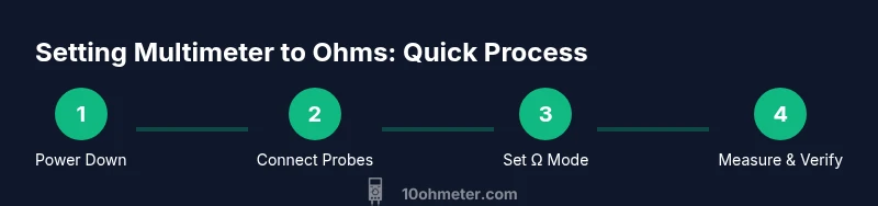
Power down and prepare
Power off the circuit and disconnect the power source. If the circuit has capacitors, wait for them to discharge or use a discharge tool. This prevents electric shock and protects the meter from surges.
Tip: Always start with a powered-off state before measuring resistance. - 2
Connect the probes correctly
Plug the black lead into COM and the red lead into the Ω jack. Ensure the leads have solid contact and are not frayed. Avoid touching metal tips while measuring.
Tip: A secure, short path reduces contact resistance that could skew results. - 3
Set the meter to ohms
Turn the dial to the Ω setting. If your meter supports auto-range, enable it; otherwise select a range that you expect to cover the unknown resistance.
Tip: Starting with a mid-range can minimize range hopping and improve stability. - 4
Zero or balance if applicable
Some meters have a relative/zero function. Short the probes and press Zero to null out lead resistance. If your meter lacks this, skip to measurement after ensuring leads are clean.
Tip: Zeroing helps remove contact lead resistance for better accuracy. - 5
Check for a baseline open
With the probes touched together, the display should read open or infinite. If it doesn’t, recheck probe contact or switch to a higher range.
Tip: A baseline open confirms the circuit is not providing a path that biases the reading. - 6
Isolate the component
Remove the component from the circuit or lift one leg so it’s not connected to other paths. This prevents parallel resistances from affecting the reading.
Tip: Isolation is critical for valid resistance measurements in dense circuits. - 7
Measure the resistance
Touch probes to the component terminals and read the value. If it fluctuates, reseat the contacts and wait a moment for stabilization.
Tip: Allow the reading to stabilize before recording the value. - 8
Compare to expected values
If you know the component’s nominal value, compare the reading and see if it falls within tolerance bands. Remember tolerances can vary (e.g., 1%–10%).
Tip: Use a known reference resistor to validate meter accuracy periodically. - 9
Re-test with verification
Place a known reference resistor across leads and confirm the reading matches within tolerance. Re-check the unknown again to ensure consistency.
Tip: Verification builds confidence in measurements across sessions. - 10
Document and store safely
Record the measurement, range used, lead condition, and ambient temperature if relevant. Power down the meter and disconnect leads before storage.
Tip: A quick log helps reproduce results on future repairs. - 11
Handle low-ohm tests carefully
Low-ohm measurements can be impacted by lead resistance; use the correct low-ohm range and consider using a dedicated fixture for stability.
Tip: Avoid prolonged contact in very low-ohm ranges to prevent heating effects. - 12
Advanced checks for electronics work
For complex boards, test resistors in isolation, then reassemble the circuit and re-measure to confirm consistent behavior across the design.
Tip: Multiple checks reduce misdiagnosis in automotive and electronics contexts.
Your Questions Answered
Can I measure resistance in-circuit, or must I remove components?
Measuring in-circuit can be done, but results may be distorted by parallel paths. For accurate resistance, isolate the component by removing it or lifting one lead before testing.
Yes, you can measure in circuit, but for accuracy, isolate the component first by lifting a leg or removing it from the circuit.
Why does my meter show OL or a high value when testing a resistor?
An open circuit or poor contact can cause OL readings. Re-seat leads, ensure you’re on the correct OHMS range, and test with a known reference to verify meter function.
OL usually means open circuit or bad contact; retry with proper range and secure connections.
How do I zero the meter when testing resistance?
Short the probes together on the Ω setting and use the meter’s zero or relative function if available. If not, re-check contact quality and proceed to measure the unknown.
Short the probes and press zero if your meter supports it; otherwise check contacts and continue.
What tolerance should I expect on common resistors?
Many resistors have tolerances of 1%, 5%, or 10%. Your meter reading should fall within that tolerance when compared to the nominal value.
Resistors usually have a tolerance of 1%, 5%, or 10%—check the component’s bands or datasheet.
When is auto-range preferable to manual range in ohms mode?
Auto-range is convenient for unknown values and quick checks. Manual range is better when you need stability and repeatable results for known values.
Auto-range is handy for unknown values; manual range gives steady readings for known values.
Are there safety steps I should follow for automotive diagnostics?
Absolutely. Disconnect power, avoid testing live circuits, and use proper PPE. When testing sensors or wiring, ensure the circuit is de-energized and components aren’t stressed by current surges.
Always ensure the circuit is de-energized and avoid measuring live electronics in vehicles.
Watch Video
Key Takeaways
- Power down before measuring resistance.
- Isolate the component for accurate readings.
- Zero offset for lead resistance improves accuracy.
- Compare against known references and tolerances.
- Document results for future repairs.