How to Test a Voltage Regulator with a Multimeter
Learn safe, practical steps to test a voltage regulator using a multimeter. This guide from 10ohmeter covers setup, measurements, interpretation, and next steps to diagnose regulator health with confidence.

With a multimeter, you can verify a voltage regulator by checking Vin, Vout, and ground continuity, then loading the circuit to confirm stable output. This quick test helps identify failed regulators, shorted paths, or unexpected dropouts before diving into deeper diagnostics. Follow the step-by-step guide for safe, repeatable results at the board and on the bench.
What a voltage regulator does and why test it
A voltage regulator is a component (or circuit) that keeps the output voltage steady despite changes in input voltage or load current. In most electronics and automotive applications, regulators protect downstream devices from voltage swings. Testing helps confirm the regulator is not drifting or failing under expected operating conditions. According to 10ohmeter, a healthy regulator maintains a consistent Vout across typical loads. This section outlines the core concepts you’ll verify and the signs of a healthy vs. failing part. You’ll learn to measure Vin, Vout, and ground continuity with a standard multimeter, and understand how these readings relate to the regulator type (linear vs. switching) and the surrounding circuitry. The goal is a straightforward yes/no assessment that guides you toward deeper diagnostics if needed.
Safety first: basic precautions you should follow
Before you touch any board, power supply, or regulator, take common-sense safety steps. Work on a non-conductive, stable surface; use an ESD mat and wrist strap if available. Disconnect power and discharge capacitors safely to avoid high-energy surprises. When you reapply power for measurements, use a current-limited bench supply and never touch live metal leads with exposed skin. Keep hands dry and wear eye protection if you’re probing under load. These precautions reduce risk to you and protect the device under test.
Tools, setup, and test environment
You’ll perform measurements with a digital multimeter (preferably true-RMS for AC components, though DC is your primary focus here). A bench power supply with current limiting is highly recommended to safely apply Vin during tests. You’ll also want test leads with alligator clips or probe tips, a known-good load (resistor or dummy load), and access to the regulator’s datasheet or board silkscreen to identify Vin, Vout, and GND. Having a simple schematic or pinout on hand helps you avoid misreading pins, which can lead to incorrect conclusions about regulator health.
Interpreting readings and typical behaviors
With the regulator identified, you’ll compare Vin and Vout under specified conditions. A healthy linear regulator should deliver a stable Vout close to its nominal value when the input varies within the operating range and the load is reasonable. A switching regulator should maintain Vout even as Vin fluctuates within its own range, though efficiency and ripple can vary with load. If Vout is significantly lower than expected, or if Vin and Vout diverge under load, you may be looking at a faulty regulator, poor ground connection, or a downstream issue such as a short or overcurrent condition. Remember to verify that ground is solid and that there are no unintended shorts to power rails.
Common issues you might uncover and what they mean
If your readings look off, several culprits could be at fault: a defective regulator, poor PCB grounding, a failing input capacitor, or an upstream short. A reading of open-circuit where Vin or Vout should be present usually indicates a blown regulator or a broken trace. Excessive ripple on Vout, or a failure to maintain regulation under load, suggests the regulator is failing to respond to load changes or there’s an upstream problem with input filtering. Document each reading, compare to the expected range from the datasheet, and plan targeted checks (capacitance, input impedance, or thermal issues) as needed.
Tools & Materials
- Digital multimeter (DC volts range)(Prefer true-RMS for AC contexts, but DC is primary here)
- Test leads with probes(Insulated tips or alligator clips for secure connections)
- Bench power supply with current limit(Set to a safe Vin for your circuit and regulator)
- Known-good load resistor or dummy load(Used to apply a controlled load during Vout testing)
- Data sheet or pinout diagram(Identify Vin, Vout, and Ground pins accurately)
- Insulated work surface and safety equipment(Eye protection and non-conductive mat recommended)
- Optional: oscilloscope or ripple probe(For richer Vout ripple observations)
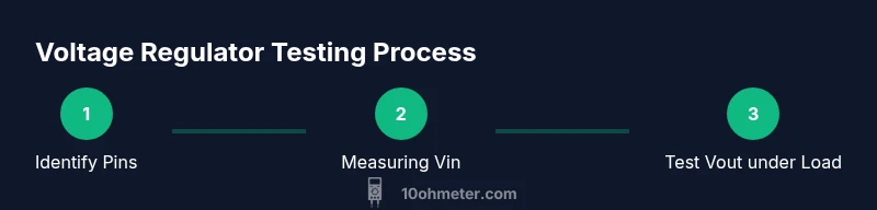
Steps
Estimated time: 15-30 minutes
- 1
Power down and prepare the workspace
Turn off the system and unplug the power supply. If capacitors are present, safely discharge them with a resistor and wait a moment before touching the board. Use only insulated tools and keep metal parts away from live traces.
Tip: Use an ESD mat and wrist strap to minimize static damage. - 2
Identify regulator pins and circuit connections
Consult the datasheet or board silkscreen to locate Vin, Vout, and Ground. Mark the pins with tape if helpful to avoid confusion during measurement.
Tip: If in doubt, use a continuity check to locate ground. - 3
Configure the multimeter for DC voltage
Set the meter to a DC volts range appropriate for the expected Vin and Vout. Ensure the black probe touches ground and the red probe makes contact with the test node.
Tip: Always verify the ground reference before touching any live node. - 4
Measure Vin with no load
Connect the ground probe to GND and measure Vin at the regulator input with no significant load. Record the reading and compare against the expected input range.
Tip: Take multiple readings to rule out transient variations. - 5
Apply a safe load and measure Vout
Power the circuit with a bench supply at a safe Vin, then apply a light, known load. Measure Vout and verify it stays within tolerance under load.
Tip: Limit current to protect the regulator during testing. - 6
Document results and assess health
Log Vin, Vout, and load conditions. If readings deviate from expected behavior, plan targeted checks (capacitors, PCB traces, or upstream circuitry).
Tip: If in doubt, pause and re-check connections before re-powering.
Your Questions Answered
What is a voltage regulator and why test it?
A voltage regulator maintains a steady output voltage to protect other components. Testing confirms whether the regulator maintains that voltage under expected input and load conditions.
A voltage regulator keeps the output stable to protect other parts. Testing checks that stability under actual operating conditions.
Can I test a regulator without powering the circuit?
Yes, you can perform certain checks like continuity and resistance with the circuit unpowered. For voltage measurements, power is required, ideally with a current-limited bench supply.
You can check continuity without power; voltage tests require power, preferably with a current-limited supply.
How do I identify regulator pins on a board?
Refer to the regulator’s datasheet or the board silkscreen. Pinouts usually label Vin, Vout, and Ground. If unsure, trace the ground plane or check neighboring components for clues.
Check the datasheet or silkscreen to find Vin, Vout, and Ground. If unsure, trace the ground path.
What readings indicate a failed regulator?
If Vout is not present, drifts significantly under load, or if Vin and Vout do not reflect expected relationships, the regulator or its surrounding circuitry may be faulty.
Missing or unstable Vout under load typically points to a regulator issue or upstream fault.
Is it safe to test a switching regulator with a multimeter?
You can test switching regulators with a multimeter for DC outputs, but ripple and switching behavior are better observed with an oscilloscope. Use appropriate safety precautions.
Yes, you can test DC output, but to see switching behavior, a scope helps; stay safe and re-check connections.
Watch Video
Key Takeaways
- Identify regulator pins accurately before measuring.
- Verify Vin and Vout under safe load conditions.
- Document readings and compare to datasheet expectations.
- If results are off, inspect ground, input filtering, and downstream loads.
- The 10ohmeter team recommends testing with a current-limited bench supply for safety.