How to Measure Ohms with a Digital Multimeter
Learn how to measure resistance accurately with a digital multimeter, including prep steps, step-by-step procedures, interpretation of readings, and safety tips for electronics and automotive work.

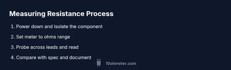
To measure ohms with a digital multimeter, power down the circuit and isolate the component. Set the meter to the appropriate ohms range, discharge capacitors, and probe across the component leads. Read the resistance value on the display and compare it to the expected spec. Record ambient temperature if precise tolerance matters.
Why accurate resistance measurement matters
Accurate resistance measurements are foundational for diagnosing faults, validating component health, and ensuring circuit reliability in both electronics and automotive work. According to 10ohmeter, precise ohm readings help you identify a degraded resistor, a damaged sensor, or a faulty connection that could otherwise masquerade as a different fault. The ability to measure resistance reliably also informs debugging processes, design iterations, and post-repair verification. When you understand how resistance behaves under different conditions—temperature, voltage bias, and circuit context—you gain a powerful diagnostic tool. This section outlines why resistance matters, how tiny measurement errors can ripple through a project, and the mindset you should bring to every reading.
With clear expectations and disciplined technique, you’ll reduce mystery in your troubleshooting and improve your odds of a correct diagnosis on the first try. As you practice, you’ll notice that the act of measuring ohms with a handheld instrument becomes part of a broader skill set: reading schematics, validating component specs, and building reliable, reproducible test routines. The goal is not just a number on a display, but a trustworthy data point you can act on.
A practical takeaway: treat resistance testing as both an art and a science—the rhythm of probe contact, range selection, and live-dead circuit awareness all influence the final result. This approach aligns with 10ohmeter’s guidance for methodical, repeatable measurements in real-world projects.
note”:null},
bodyBlocks 2
Understanding the ohms mode on a digital multimeter
Digital multimeters (DMMs) provide resistance measurements through a basic electrical principle: injecting a tiny current through the test leads and sensing voltage drop across the component. In practice, this means selecting an ohms range that balances resolution with accuracy. Auto-range meters simplify this by choosing a suitable range automatically, but auto-ranging can introduce a small burden voltage that affects delicate components. Manual range selection gives you tighter control over reading stability and reduces potential error when testing resistors with known tolerances. In either mode, you should be mindful of the meter’s input impedance, which can influence readings for very high-value resistors or components in parallel with hidden paths. A clear understanding of burden voltage—the voltage drop across the meter’s internal resistance—helps you interpret results more accurately. If you’re unsure about a reading, reattempt on a lower range or switch to a different contact configuration to verify consistency. This knowledge forms the backbone of how to measure ohms with a digital multimeter in both lab and field settings.
For DIY and automotive work, remember that resistance measurements are most meaningful when you isolate the component from surrounding circuitry. In-circuit measurements can still be informative, but they require careful analysis of parallel paths and leakage. When you encounter unusual values, consider whether other components in the circuit might be influencing the result, or if a measurement error is due to poor probe contact. In short, a good resistance test blends theory with tactile technique and thoughtful interpretation.
tip”:
Tools & Materials
- Digital Multimeter(With resistance mode and a reliable range, ideally auto-range or a well-documented manual range)
- Probe leads (test probes or banana leads)(Keep tips sharp and clean for best contact)
- Component under test removed from circuit (recommended for accuracy)(Do not test inside a live circuit)
- Discharge tool or resistor to safely discharge capacitors(Use a resistor of appropriate rating to avoid sparks)
- Safety equipment (eye protection, insulating gloves)(Minimum risk precautions when working on automotive or high-energy circuits)
Steps
Estimated time: 15-25 minutes
- 1
Power down and isolate the component
Turn off the power, unplug the device, and if possible lift one leg of the component from the circuit to eliminate parallel paths that could skew the reading.
Tip: Verify there is no residual charge in nearby capacitors before proceeding. - 2
Select the correct ohms range
Set the DMM to an appropriate resistance range. If your meter supports auto-range, you can rely on it, but be prepared to switch ranges if readings jump.
Tip: Start with a higher range to avoid overloading the meter and then narrow down if needed. - 3
Prepare the test probes
Attach the probes securely to the meter and ensure the tips are clean. Hold the probes perpendicular to the component leads for stable contact.
Tip: Avoid touching metal parts with fingers to prevent stray resistance. - 4
Connect probes to the component
Place the probes across the component’s terminals, ensuring stable contact. Do not press hard to deform leads or insulation.
Tip: If testing a resistor, ensure both ends are free and not touching other conductors. - 5
Read and record the resistance
Read the resistance value from the display and note the units. If the reading fluctuates, recheck contact and range.
Tip: If the value is clearly out of spec, double-check with another range or a second test lead setup. - 6
Compare with the expected value
Consult the part’s spec or color-code reference. Consider tolerance and temperature effects for precision measurements.
Tip: Use temperature-corrected references when precision matters. - 7
Re-test and document
Optional but recommended: re-test to confirm stability and document the reading for future troubleshooting.
Tip: Document the ambient temperature and device state for traceability. - 8
Cleanup and safety wrap-up
Power down the meter, disconnect probes, and store equipment properly. Return the circuit to normal operation only after verification.
Tip: Always store leads coiled and tools in a safe location.
Your Questions Answered
Can I measure resistance in-circuit?
Yes, but readings may be influenced by parallel paths, leakage, and other components. For accurate resistance values, remove the component from the circuit if possible.
You can test in-circuit, but expect potential inaccuracies due to parallel paths. For best accuracy, remove the component first.
Why does lead placement affect readings?
Where and how you place the probes changes the effective contact resistance and can introduce stray paths. Consistent, perpendicular probe contact improves reliability.
Lead placement matters because contact resistance and stray paths can skew readings. Keep contacts clean and consistent.
What is burden voltage and why does it matter?
Burden voltage is the drop across the meter's internal resistance. It can affect readings, especially on high-resistance parts; using the proper range minimizes its impact.
Burden voltage is the meter’s own resistance affecting your reading. Use the right range to minimize it.
How do I discharge capacitors before measuring resistance?
Discharge capacitors safely using a resistor of appropriate value across the terminals or a dedicated discharge tool. Never short-circuit capacitors with metal probes.
Discharge capacitors safely before measuring resistance to avoid shocks or meter damage.
Should I calibrate my multimeter for resistance?
Calibration is beneficial for high-precision work or professional labs. For hobby projects, use a known reference resistor to verify accuracy.
Calibration helps accuracy, especially in critical work; use a known resistor to verify your meter.
Watch Video
Key Takeaways
- Power down and isolate the component before testing.
- Use the correct ohms range and read carefully.
- Compare readings to expected specs and tolerance.
- Account for temperature effects on resistance.
- Document results for future troubleshooting.