What Setting on Multimeter to Test Capacitor: A Practical Guide
Learn the exact multimeter setting to test capacitors, how to discharge safely, and interpret readings. This practical guide covers capacitance tests, ESR checks, in-circuit considerations, and common mistakes for DIY electronics and automotive work.

To test a capacitor with a multimeter, you’ll typically use the capacitance setting (often labeled μF) or an ESR-capable tester. Begin by discharging the capacitor safely, then select the correct test range, and compare the reading to the capacitor’s rated value or tolerance. If your meter lacks capacitance, use an ohms check as a supplementary guide.
Understanding what we measure when testing capacitors
A capacitor stores electric charge, and its primary characteristics are capacitance (measured in microfarads, μF, or nanofarads, nF) and leakage. When you test a capacitor with a multimeter, you’re verifying whether it still holds the expected charge and can respond to voltage changes as designed. Good capacitors show readings close to their rated value with minimal drift, while bad ones exhibit low capacitance, excessive leakage, or erratic behavior under test. Temperature and aging can shift measurements, so consider a tolerance window typical for the capacitor type. For automotive and electronics tasks, this helps isolate failed parts in a circuit and reduces time chasing intermittents.
In practice, you’ll use capacitance testing for solid-state capacitors like ceramic and film types, and ESR/ resistance checks for electrolytics and high-ESR devices. Modern multimeters sometimes combine capacitance, resistance, and sometimes ESR modes, giving you multiple angles to assess a suspect capacitor. Always consult the capacitor’s datasheet for nominal values and acceptable tolerance to avoid misinterpreting readings.
Choosing the right measurement approach: capacitance vs ESR and resistance
Capacitance mode directly measures the stored charge capacity, which is the most straightforward test for a capacitor’s health. ESR (equivalent series resistance) testing, available on some meters or as a standalone tool, reveals internal degradation that can happen before capacitance drops noticeably. If your meter only offers a resistance test, you can still gain useful information: an open circuit (OL) or infinite resistance and no charging response suggests a failed capacitor, while a very low resistance that stabilizes hints at a short or leakage path. The goal is to compare measured values to the component’s nominal values under controlled conditions.
Note that ESR measurements are most meaningful when done with a meter that supports ESR or with a specialized instrument. For in-circuit testing, component interactions may skew results, so remove the capacitor if precision matters. Always discharge the capacitor before testing and avoid touching leads with bare hands to minimize shock risk.
Safe discharge and handling before testing
Before any test, ensure power is off and the device is unplugged. Capacitors can hold dangerous charges even after power removal. Use a proper discharge method: a resistor of appropriate value (commonly 1 kΩ to 10 kΩ, depending on the capacitor size) connected across the terminals for a few seconds, or a dedicated discharge tool. Shorting directly with a metal object can damage the capacitor or your meter; instead, use a resistor to limit current and monitor any spark or heat. After discharging, verify there is no residual voltage with the meter on its voltage range. If you must handle power-sensitive capacitors (like large electrolytics in power supplies), wear eye protection and work on an isolated bench.
How to test: using the capacitance setting
To perform a capacitance test, remove the capacitor from the circuit if possible, or isolate it so other components don’t influence the reading. Connect the meter’s probes to the capacitor terminals, ensuring correct polarity for polarized electrolytics (observe the longer lead as positive when applicable). Set the meter to the capacitance range (μF). Read the displayed value and compare it to the capacitor’s labeled value and tolerance. If the value is within tolerance, the capacitor is likely healthy; if it’s low, leaky, or shows instability, it may need replacement. For non-polarized capacitors, orientation of probes does not affect the result, but consistent probe placement helps repeatability.
Understanding readings: tolerance, temperature, and aging
Capacitors are manufactured with tolerance ranges (for example ±10%). Real-world readings may drift due to ambient temperature, voltage history, and aging. A new capacitor may measure slightly different from its nominal value but still be within tolerance. The capacitor’s series and dielectric type also influence performance; ceramic capacitors, for example, can exhibit wide tolerances at higher values. When readings diverge significantly beyond tolerance, or readings drift with repeated tests, the component is a strong candidate for replacement. Record readings under consistent conditions (temperature, voltage history) to compare across tests.
In-circuit testing considerations
Testing a capacitor while it remains in-circuit introduces parallel paths with other components (resistors, inductors, diodes, ICs) that can distort readings. If possible, remove the capacitor from the circuit to obtain an accurate capacitance or ESR value. If removal isn’t practical, you can perform a rough check by isolating one leg with a jumper or by lifting one connection, then retesting. Always note how the circuit’s power state and other components may affect results. Document the test conditions, including whether the device was powered at any point during measurement.
Interpreting failed readings and next steps
A failed capacitance reading—significantly lower than the nominal value—often indicates a failed capacitor due to dielectric breakdown, moisture ingress, or aging. A reading close to zero or an open circuit implies an open capacitor. High ESR readings point to internal degradation, especially in electrolytics. If a capacitor looks bad, replace it and retest the circuit to verify behavior. In some cases, the circuit around the capacitor may be causing leakage; inspect nearby solder joints and related components for damage or corrosion. When in doubt, compare readings against a known-good identical capacitor to confirm suspicion.
Alternatives when the meter lacks a capacitance range
If your multimeter does not support a capacitance function, you can still perform useful checks with a few approaches. One method is the RC time constant test: apply a small known voltage and observe the charge time using the voltage or resistance range to infer capacitance. Another approach is ESR testing with a specialized meter or adapter. For highly critical work, consider using a dedicated LCR meter or an oscilloscope-based test to analyze charging curves. In all cases, de-energize circuits and discharge capacitors fully before testing.
Common mistakes and how to avoid them
- Testing a charged capacitor: always discharge first to prevent shocks and false readings. - Connecting the meter in-circuit without isolating other components can skew results. - Using the wrong scale or failing to set the meter to the correct capacitance range leads to inaccurate values. - Ignoring temperature and tolerance can cause misinterpretation. - Forgetting to discharge safety precautions can cause injury; wear eye protection and use insulated tools. By following a consistent procedure, you minimize misreads and get reliable data.
Safety and maintenance best practices
Capacitor testing involves handling live components and potentially hazardous voltages. Always power down equipment, unplug from power sources, and discharge capacitors safely. Use PPE such as safety goggles and insulated tools, and work on a non-conductive, stable surface. Keep your multimeter’s probes in good condition, inspect leads for cracks, and store tools away from moisture. Maintain a clean workspace, and label any failed parts clearly for replacement. Regular calibration of your meter ensures accuracy over time.
Tools & Materials
- Digital multimeter with capacitance function(Capacitance measurement range (μF) preferred)
- Test capacitor(s) with known values for practice(Include at least one electrolytic and one ceramic/film)
- Discharge tool or resistor (1 kΩ – 10 kΩ)(Safe discharge across capacitor leads)
- Alligator clips or probe adapters(Helps isolate and connect securely)
- Safety goggles and insulated gloves(Personal protection when handling charged capacitors)
- insulated workspace mat(Reduces static and provides cushion)
- Soldering iron and wire cutters(For removing/isolating components in-circuit)
Steps
Estimated time: 25-40 minutes
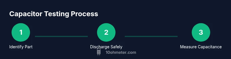
- 1
Identify capacitor type and prepare test
Locate the capacitor to test, verify its value on the body or datasheet, and select the appropriate test method. If electrolytic, note polarity and discharge considerations. Prepare the workspace to avoid shorts and accidental contact with live circuits.
Tip: Double-check polarity on polarized caps before testing to prevent damage. - 2
Power down and discharge safely
Power off the device and unplug from any power source. Discharge the capacitor with a resistor across its terminals for several seconds, ensuring slow, controlled current flow to avoid sparks.
Tip: Never short a capacitor without a resistor; this can cause a high current surge. - 3
Isolate the capacitor from the circuit
If possible, lift one lead or remove the capacitor from the circuit to avoid parallel paths that skew readings. This helps ensure measured capacitance or ESR reflects the component itself.
Tip: Keep track of lead positions to reassemble correctly. - 4
Connect the meter probes to the capacitor
Attach the meter probes to the capacitor leads, ensuring solid contact. For polarized capacitors, connect the positive probe to the marked positive lead. Avoid touching the metal tips during measurement.
Tip: Use alligator clips for a stable connection. - 5
Set the meter to capacitance mode and read
Switch the meter to the capacitance setting and observe the displayed value. If the meter shows overload or no reading, recheck connections and ensure the capacitor is discharged.
Tip: Allow the meter to settle for a couple of seconds to stabilize the reading. - 6
Compare to rated value and tolerance
Compare the measured capacitance to the capacitor’s rated value and tolerance from the datasheet. A reading within tolerance indicates a healthy capacitor; a substantial deviation suggests replacement.
Tip: Document the reading and reference value for future repair records. - 7
Interpret ESR or resistance if needed
If ESR mode is available, test the capacitor’s ESR. A high ESR indicates degraded dielectric or internal leaks, even if capacitance appears acceptable. If ESR is normal but capacitance is off, the capacitor may be aging.
Tip: Use ESR readings in conjunction with capacitance measurements for a complete assessment.
Your Questions Answered
What setting on a multimeter should I use to test a capacitor?
Use the capacitance (μF) setting to measure the capacitor’s value. If your meter has ESR, you can test ESR for degradation. Always discharge first and remove the capacitor from the circuit for the most accurate readings.
Use the capacitance setting to measure the capacitor’s value. If your meter supports ESR, you can test that too; always discharge first and remove the part from the circuit for accuracy.
Can I test a capacitor in-circuit?
In-circuit testing can be misleading due to parallel components. If possible, remove the capacitor from the circuit before testing. If removal isn’t feasible, isolate the capacitor lead as much as possible and note potential interference.
In-circuit testing can be misleading because other parts affect the reading. If you can, remove the capacitor first; if not, isolate one lead and note potential interference.
What readings indicate a bad capacitor?
A capacitance value far outside the rated tolerance, very high leakage (high ESR), or readings that drift significantly with time indicate a failing capacitor. An open circuit (no continuity) also points to failure.
Capacitance far from the rated value, high ESR, or readings that drift indicate a bad capacitor. An open circuit also means failure.
What if my meter doesn’t have a capacitance range?
Without capacitance range, perform an ESR/ resistance check if possible or use a known-good capacitor for comparison. Alternatively, consider an inexpensive LCR meter for more accurate tests.
If your meter lacks capacitance testing, use ESR or resistance checks or compare with a known-good capacitor, or get an LCR meter for accuracy.
Are there safety concerns I should be aware of?
Always unplug power, discharge capacitors, and wear safety gear. Large capacitors can release a harmful charge; never touch exposed leads. Work on a non-conductive surface and keep liquids away from the workspace.
Unplug power, discharge capacitors, and wear safety gear. Large capacitors can shock you, so keep the area dry and non-conductive.
Watch Video
Key Takeaways
- Discharge capacitors before testing to stay safe.
- Use capacitance mode for direct value checks; ESR adds health insight.
- Remove the capacitor from circuit when possible for accurate results.
- Compare readings against nominal values and tolerance from the datasheet.
- Document results and understand that aging affects accuracy.