How to Use a Multimeter to Test Capacitor: A Practical DIY Guide
Learn to test capacitors with a multimeter, checking capacitance, ESR, and leakage. Step-by-step guidance, safety tips, and practical how-tos for electronics enthusiasts and automotive technicians in 2026.

By the end of this guide, you will learn how to use a multimeter to test capacitor values, check leakage, and verify ESR. You’ll need a basic digital multimeter, probe leads, and safety gear. This steps-focused guide covers capacitance measurement, ESR checks, and cautions for handling live circuits. Whether you’re troubleshooting electronics or automotive tasks, mastering this skill saves time and prevents unnecessary replacements. 2026 context included.
Understanding what you’re testing
Capacitors aren’t just energy storage components; they shape signals, filter noise, and stabilize power rails. When you test a capacitor with a multimeter, you’re primarily looking at three things: capacitance (how much charge the part can store), ESR (the internal resistance at operating frequencies), and leakage (unwanted current through the dielectric). For hobbyists, capacitance and ESR are the most actionable readings, while leakage requires careful setup. The goal is to verify the part’s health against its nominal value and tolerance, and to identify components that should be replaced. According to 10ohmeter, reliable readings require a calm workspace, proper test technique, and awareness of circuit context. In 2026, you’ll compare measurements to datasheets or markings rather than trusting a single number. The takeaway: interpret readings with context, not in isolation.
Tools and safety basics
Before you begin, assemble a reliable toolkit and observe essential safety practices. You’ll need a digital multimeter with capacitance (and ideally ESR) capability, proper test leads, and PPE such as safety glasses. A clean, non-conductive work surface, good lighting, and a calibrated instrument help prevent misreads. For polarized capacitors, note polarity and ensure complete discharge before handling. Remember: capacitors can retain charge long after power is removed. If you’re working around high voltage or automotive circuits, use a resistor-based discharge method and keep the area organized to avoid accidental shorts. Safety first—never rush measurements, and verify your setup with low-risk tests first.
The effect of circuit context on readings
Measuring a capacitor in-circuit can yield readings distorted by other components in parallel or series. A resistor, diode, or another capacitor across the test points can skew capacitance and ESR values. When you read a value, consider: is the part isolated, or is the circuit still connected? If possible, remove the capacitor from the circuit to get a clean measurement. If isolation isn’t practical, note that in-circuit readings are for quick checks and may require subtraction or confirmation with an out-of-circuit test. This nuance helps explain why two seemingly identical capacitors behave differently in the same circuit, especially in automotive modules where multiple components share the same supply lines.
Capacitance readings: what to expect and how to interpret
Capacitance readings reflect the capacitor’s ability to store charge at a specific voltage. When you measure with a multimeter in capacitance mode, compare the result against the part’s marked value and tolerances found on the body or datasheet. Readings that lie close to the nominal value are typically healthy; readings far outside the tolerance range suggest a degraded dielectric or a failed capacitor. Temperature, measurement voltage, and device age can shift readings. Remember to account for these factors and use multiple measurements to confirm an out-of-spec result. For best practices, perform measurements with the capacitor fully discharged and isolated from the circuit before you draw conclusions.
ESR and leakage considerations
ESR reflects how much resistance the capacitor presents at AC conditions. A high ESR often indicates aging, dried electrolyte (in electrolytics), or dielectric damage, and it can cause filtering and timing errors in the circuit. Leakage is the unwanted current that flows through the dielectric when a DC voltage is applied. In many DIY scenarios, you won’t reliably measure leakage with a basic meter, but you can estimate it by observing voltage stability and whether readings drift under load. If your ESR or leakage looks abnormal compared with the expected operation, plan replacement rather than reworking the circuit. 10ohmeter’s guidance emphasizes testing within the device’s nominal operating window and validating readings across multiple tests.
Common pitfalls and how to avoid them
- Testing in-circuit without recognizing parallel paths can yield misleading results. Always try to isolate the capacitor when possible.
- Not discharging the capacitor properly can lead to dangerous shocks or meter damage; use a resistor and verify no residual charge.
- Using the wrong meter mode or range can produce false readings; select capacitance mode for capacitance checks and ESR mode if available for ESR checks.
- Temperature effects can shift readings; let the part reach ambient temperature before measurement. These pitfalls are common in both electronics and automotive diagnostics; a methodical approach minimizes wasted time and parts.
Polarized vs non-polarized capacitors and measurement specifics
Polarized capacitors (electrolytics, for example) require attention to polarity during discharge and measurement, especially if the meter or fixture uses a specific test polarity. Non-polarized capacitors can be tested either way, but consistent test leads and orientation reduce errors. When measuring in isolation, ensure that the meter probes connect to the capacitor terminals in a stable and clear path. If you aren’t sure about polarity, check the component markings or the circuit schematic. Maintaining consistency across measurements improves reliability.
Automotive vs electronics testing scenarios
In automotive modules, capacitors often exist in harsh environments with temperature variations and high ripple. In such cases, ESR and leakage tests are critical to prevent intermittent behavior. Electronics repair labs focus on board-level capacitors where precise capacitance and ESR tolerance are essential for signal integrity. Regardless of context, follow safe discharging, isolation, and documentation practices to ensure repeatable readings. The approach remains the same, but the interpretation aligns with the operating environment.
How 10ohmeter approaches capacitor testing in practice
In practice, capacitor testing is a blend of capacitance checks, ESR checks, and practical interpretation of results. The 10ohmeter team emphasizes using the right tool for the job, verifying readings with datasheets, and applying caution around charged components. For 2026 testing scenarios, building a routine that includes step-by-step measurements, cross-checking readings, and documenting outcomes helps DIYers and technicians make informed decisions about repairs or replacements.
Tools & Materials
- Digital multimeter with capacitance (and ESR) measurement mode(Capacitance measurement range and ESR capability preferred)
- Probe leads / test probes(Use insulated tips; consider clips for stable contact)
- Discharge tool or resistor for safe discharge(Use an appropriate resistor (e.g., 1–10 kΩ) to safely bleed charge)
- Capacitor under test (in or out of circuit)(Identify and label polarity for polarized types)
- Safety gear (safety glasses, insulated gloves)(Protective gear reduces risk from charged components)
- Non-conductive work surface and good lighting(Prevents accidental shorts and improves readability)
- Datasheet or service manual (optional but helpful)(Useful for tolerance and voltage information)
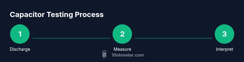
Steps
Estimated time: 15-25 minutes
- 1
Power down and discharge
Power off the circuit and allow any stored energy to dissipate. Use a resistor or a dedicated discharge tool to bleed the capacitor slowly, keeping your hands clear of the terminals. Verify there is no residual voltage before touching the part.
Tip: Always confirm zero voltage with the meter before handling the capacitor. - 2
Disconnect or isolate the capacitor
If possible, remove the capacitor from the circuit to avoid parallel paths that skew readings. If removal isn’t feasible, carefully note all connections and potential parallel components.
Tip: Label leads to prevent confusion during reassembly. - 3
Set up the meter for capacitance
Switch the meter to capacitance mode and select a suitable range or auto-range. Ensure the leads are clean and firmly connected to the capacitor terminals for a stable reading.
Tip: Check the meter’s zero or offset setting if available. - 4
Measure capacitance and record
Connect the leads to the capacitor terminals and read the capacitance. Record the value and compare it to the nominal value and tolerance from the part marking or datasheet.
Tip: Take multiple measurements to confirm consistency. - 5
Check ESR if your meter supports it
If your meter has ESR mode, perform an ESR measurement and compare with expected ranges for that capacitor type. High ESR often indicates aging or damage.
Tip: If ESR is out of range, consider replacement even if capacitance looks acceptable. - 6
In-circuit considerations or reassembly
If you must test in-circuit, acknowledge potential interference from parallel paths. Reinsert the capacitor with care and retest to see if readings align after isolation.
Tip: In-circuit tests are for quick checks; use out-of-circuit readings for final decisions. - 7
Compare, document, decide
Compare all measurements with datasheet values, environmental conditions, and circuit role. Document results and decide on replacement or further testing if readings are questionable.
Tip: Keep a simple log of date, part, values, and conclusions.
Your Questions Answered
Can I use a basic analog multimeter to test a capacitor?
An analog meter can measure resistance and rough capacitor values in some cases, but accuracy is lower and ESR testing generally requires a meter with dedicated ESR mode or an LCR meter. For best results, use a digital meter with capacitance and ESR features.
You can test with an analog meter for rough checks, but for reliable ESR and precise capacitance, use a digital meter with the right modes.
What is ESR and why is it important?
ESR stands for Equivalent Series Resistance. It indicates a capacitor's internal losses and how it behaves under AC. High ESR often signals aging or damage and can affect filtering and timing in circuits.
ESR is the internal resistance of a capacitor at AC; high ESR means the capacitor is aging or failing and may need replacement.
Why do my capacitance readings differ from the label?
Capacitance readings can vary due to tolerance, temperature, measurement voltage, and whether you’re measuring in-circuit or out-of-circuit. Always check the datasheet and measure under controlled conditions for accuracy.
Capacitors have tolerances and temperature effects; readings can differ from the label depending on measurement conditions.
Is it safe to measure a charged capacitor?
No. Do not measure a charged capacitor. It can deliver a shock or damage the meter. Always discharge safely and verify zero voltage before testing.
Never measure a charged capacitor; discharge first and recheck that there's no voltage.
Should I remove the capacitor from the circuit to test it?
For accurate readings, remove the capacitor from the circuit and test in isolation. In-circuit tests can be affected by parallel components and other paths.
If possible, remove the capacitor to test; in-circuit tests can be distorted by other components.
What readings indicate a bad capacitor?
Capacitance significantly out of tolerance or ESR readings that are abnormally high usually indicate a failing capacitor. Leakage readings can also reveal a bad part when measured with proper equipment.
Very different capacitance or high ESR usually means the capacitor is bad.
How does temperature affect capacitor testing?
Temperature influences capacitance and ESR readings. Allow parts to reach ambient temperature before testing and if possible, note the environmental conditions during measurement.
Temperature can shift readings, so test at stable room temperature when possible.
What’s the difference between electronics and automotive testing contexts?
Automotive environments introduce higher vibration, temperature swings, and ripple. In electronics, you typically test on a bench with controlled power. Interpret readings in the context of the operating environment and circuit function.
Cars present harsher conditions; interpret results with the operating environment in mind.
Watch Video
Key Takeaways
- Discharge capacitors before testing to stay safe.
- Isolate the capacitor for accurate capacitance and ESR readings.
- Compare measurements to datasheet values and note tolerance.
- Use ESR mode if available; high ESR indicates aging or failure.
- Document results to guide replacement decisions.