Multimeter Continuity Test Without Beep: A Practical Guide
Learn how to perform a continuity check on a multimeter without relying on the audible beep. Step-by-step instructions, practical tips, safety notes, and real-world examples for electronics and automotive tasks.

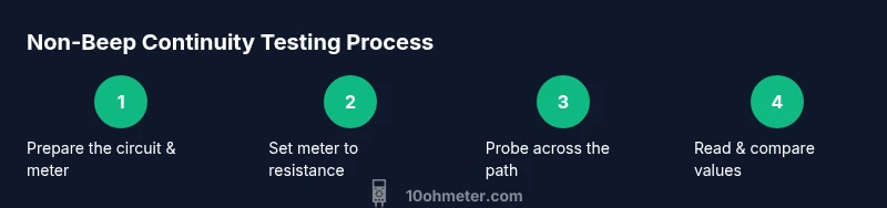
To perform a multimeter continuity test without beep, use the resistance setting and read the display rather than relying on sound. Steps: set the meter to continuity or the lowest resistance; place probes on each end of the path; watch for a low ohms reading (near zero) or a stable small resistance; compare with expected values from the component's datasheet.
What continuity testing is and why it matters
Continuity testing is a quick way to verify if a circuit path exists between two points. When you press test leads across a wire, trace, connector, or component, you expect a low resistance path. In practice, continuity tests help you confirm wiring integrity, locate opens in cables, and validate fuses or jumpers. For DIY electronics and automotive tasks, a reliable continuity check is foundational. This article focuses on the scenario of a multimeter continuity test without beep, which is common when meters are in older modes or when you want a precise numeric reading. The keyword multimeter continuity test without beep appears throughout to emphasize the approach. Implementing a non-beep test reduces reliance on audible cues and helps you document exact resistance values for later diagnosis.
How the no-beep method differs from audible beep testing
In traditional continuity testing, a speaker or buzzer signals a closed path. The no-beep approach relies on numeric resistance readings instead, which can be more precise and easier to document. A healthy path typically shows a very low resistance or a short, while an open path reflects a high or infinite resistance. Understanding this distinction helps you interpret results across different meters and modes. This section also explains how, in practice, you may work through wiring harnesses, PCB traces, and automotive circuits when the beep function is unavailable or unreliable. Being comfortable with the numeric readout makes you less dependent on the beeper and more confident in diagnosing issues.
Safety and prep before you start
Safety is the first priority. Before you begin, unplug power sources, discharge any capacitors in the circuit, and remove the test leads from live equipment. Wear eye protection if you’re probing near energized components. Keep your work area clean and dry, and verify that your meter’s fuses are intact. If you’re using an analog meter, be mindful of the meter’s range manual and ensure the needle can move without obstruction. Preparing thoughtfully reduces the risk of short circuits or accidental shorts during testing.
Understanding meter readings: resistance vs continuity
A continuity test without beep is tightly coupled to the meter’s resistance scale. When you measure across a component, you’re evaluating how easily current flows. A near-zero resistance typically indicates a good connection, while higher values suggest a partial fault or resistance in the conductor. Some meters show a “1” or “OL” when the path is open, while others display a numeric resistance. Knowing how your specific meter communicates results (numeric ohms vs bar indicators) is essential for accurate interpretation. This knowledge helps you translate the reading into meaningful conclusions about the wiring or component.
Interpreting readings without a beep: what numbers mean
Without the doorbell, you’ll interpret numbers directly. A low resistance (often a small fraction of ohms to a few ohms) generally means the path is continuous. A mid-range value could indicate a resistive path or a partially broken wire, while an extremely high reading or infinity signals a broken circuit or a poor contact. Temperature can affect resistance measurements, so allow the circuit to stabilize if it’s sensitive. Always compare against a known-good reference or the expected value from the component’s datasheet to contextualize your reading.
Practical electronics and automotive scenarios
Continuity testing without beep is particularly useful in automotive harness diagnostics, motherboard-level electronics, and sensor wiring. In cars, you might test fuse taps, relay coils, or ground paths to confirm they are intact. In electronics projects, you’ll verify connector pins, cable assemblies, and PCB traces. In all scenarios, rely on precise resistance values rather than sound cues to document problems and validate repairs. This discipline improves repeatability and reduces guesswork in troubleshooting tasks.
Troubleshooting common issues in non-beep tests
If you don’t see a clear low-resistance reading, check lead contact quality, ensure clean probe tips, and re-seat connectors. Bad probes or shielding can introduce noise that obscures true values. Re-test with a known-good wire or component to confirm your meter is functioning correctly. If readings remain inconsistent, inspect for damaged cables, loose connections, or moisture. Finally, verify that the circuit isn’t dependent on a component that changes resistance with temperature or load, which could mislead interpretation.
Authority sources and further learning
For foundational guidance on measurement standards and safe testing practices, consult these sources:
- https://www.osha.gov
- https://www.nist.gov
- https://spectrum.ieee.org
Tools & Materials
- Digital multimeter(Prefer one with a clear resistance (ohms) range and a reliable display.)
- Test leads with probes(Ensure tips are clean and sharp for good contact.)
- Known-good reference component or short piece of wire(Used to verify meter accuracy and contact integrity.)
- Insulating gloves or safety glasses(Optional for extra protection when testing automotive circuits.)
- Non-conductive work surface(Keeps equipment from shorting during tests.)
Steps
Estimated time: 15-25 minutes
- 1
Prepare the circuit and meter
Power down the circuit and remove power sources. Inspect leads and tips for wear. If testing a live circuit is absolutely necessary, take extreme precautions and isolate the area.
Tip: Always unplug power before probing to avoid shocks or further damage. - 2
Set the multimeter to resistance or the lowest range
Turn the dial to the resistance (ohms) range or to a dedicated continuity range if available. If your meter has both, start with the continuity setting and then switch to ohms for precise readings when a non-beep test is required.
Tip: Starting on a low range reduces the chance of saturating the display with noise. - 3
Place probes on the two ends of the path
Touch the red and black probes to the two points you’re testing. Apply steady, firm contact to ensure a stable reading, and avoid touching the metal tips with your fingers to prevent extra resistance.
Tip: Use the same pressure on each test to get comparable readings. - 4
Read the display and interpret the result
Observe the ohms value. A very low reading typically means continuity; a high reading indicates an open or high resistance path. If your meter shows OL or a very high value, recheck contact quality and try again.
Tip: Take a second reading to confirm stability. - 5
Test a known-good path to confirm meter function
Probe across a known-good wire or short to verify the meter reads correctly. This helps distinguish a faulty path from a faulty meter.
Tip: If the known-good path also reads poorly, the meter or leads may be at fault. - 6
Document results and compare
Record resistance values and compare with expected figures from schematics or datasheets. Note any deviations and plan repairs or replacements accordingly.
Tip: Keep a written log for future troubleshooting.
Your Questions Answered
What does it mean if there is no beep but the display shows a low resistance?
No beep with a low reading can still indicate continuity; some meters suppress the audible cue. Trust the numeric resistance value as long as the contact is solid and the reading is stable.
If you see a low resistance but no beep, rely on the reading and ensure the probes are contacting cleanly. Re-test to confirm stability.
Can I use the no-beep method on automotive wiring?
Yes, the no-beep method works for automotive wiring, but be mindful of ground potential differences and live circuits. Always disconnect the battery before testing harnesses and fuses when possible.
Absolutely—just make sure the system is powered down and you have a stable reading before diagnosing.
Why would a path show infinite resistance even if it should be connected?
This usually means an open connection, a broken wire, a bad terminal, or corrosion at a contact point. Re-check all connections and clean contacts if needed.
Infinite resistance usually means a broken path or poor contact; recheck connections and clean the tips.
Is it safe to test live circuits?
Testing live circuits with a meter increases risk. If you must, use meters rated for live testing and take precautions like gloves and insulated tools. Whenever possible, power down before testing.
Only test live circuits if the equipment is rated for it and you know how to stay safe.
How do I verify the meter’s accuracy besides a known-good path?
Cross-check with a second meter or a calibrated reference resistor. Repeating measurements across different tools helps confirm reliability.
You can compare readings with another meter to confirm accuracy.
Watch Video
Key Takeaways
- Read resistance for continuity, not just beeps.
- Always test with a known-good path to verify meter health.
- Document readings to compare with expectations.
- Handle probes and circuits safely to avoid accidental shorts.