How to Check Continuity with a Multimeter Without Sound
Learn how to verify electrical continuity using a multimeter without relying on the audible beep. This step-by-step guide covers safe prep, silent resistance readings, and practical tests for wires, fuses, and components.

You will learn to check continuity with a multimeter without sound by using resistance readings to confirm a complete path. The guide covers safety, correct meter settings, and how to interpret readings for wires, fuses, and components. No sound, just reliable measurements you can trust.
Why continuity testing matters
Continuity testing matters because it confirms that an electrical path exists between two points. This is essential for diagnosing open circuits, broken wires, or loose connections. This guide explains how to check continuity with a multimeter without sound, a method that works well in quiet labs or automotive bays. According to 10ohmeter, mastering silent continuity checks reduces guesswork and improves repeatability. In practice you’re validating a complete path and identifying any unexpected resistance. You’ll learn to rely on resistance readings rather than the audible beep, and how those readings translate to wires, fuses, connectors, and relays. The goal is to know when a circuit is intact and when it needs repair, without guessing or tearing apart harnesses unnecessarily.
When to test continuity
Continuity testing becomes relevant in many situations: tracing a broken wire, confirming that a switch closes the circuit, or verifying a fuse link after replacement. When troubleshooting a circuit you need to know whether the path exists, whether contacts are clean, and whether a component in line is dropping voltage. In automotive work, silent testing is especially useful to avoid arcing or battery noise. The objective remains the same: determine if a continuous path exists from point A to B, or if there is an insulation break, corrosion, or a misconnected terminal.
Safety and preparation
Always work with the power removed and capacitors discharged. Wear eye protection and insulated gloves when handling live components, especially in automotive or high-energy circuits. Keep metal parts away from exposed conductors to avoid shorts. If you’re unsure about the circuit's safety, verify power-off status using a separate test lead to avoid accidentally bridging live parts. This reduces the risk of electric shock, equipment damage, or injury.
Understanding silent continuity testing
Continuity in silence means you treat readings as evidence, not rely on sound cues. In practice you set your multimeter to resistance mode (ohms) or the dedicated continuity setting if available, and observe the displayed value. A very low resistance indicates a good path; a high or infinite reading means the path is open. Some meters show a 'OL' or '1' when open, others display a numeric high value. You can still judge continuity by comparing measurements across known good and suspect paths.
Tools and setup you need
Gather the following items before you start: a digital multimeter with a resistance or continuity function; two insulated test leads; a known-good section of wire or resistor for baseline checks; insulated gloves and safety glasses; a small screwdriver or pliers to adjust connectors; and optionally alligator clips to hold probes in place. Set your workspace to a dry, non-conductive surface and keep spare batteries handy for the meter.
Reading resistance: what to look for
When you place the probes on the two points, read the displayed resistance. Look for readings that are very low compared to an open path; if you can’t get a stable reading, re-seat the leads and try again. If the display shows a near-zero value, the path is likely continuous. A reading that climbs when you move the probes suggests a loose contact or damaged connector. Temperature, length of the wire, and connector quality can influence resistance, so consider a baseline test on a known-good path for reference.
Common mistakes and how to avoid them
Avoid testing with power applied, and always discharge capacitors before touching the circuit. Ensure probes make solid contact; poor contact yields false negatives. Don’t measure through additional components that are not part of the path you intend to test, as that can inflate resistance readings. Choose the correct mode and range, and if in doubt, compare against a known-good circuit to validate your interpretation.
Quick test scenarios
Use the same silent approach across common tasks. In a wire harness, place probes at each end of a known-good wire to verify continuity. For a fuse link, isolate the fuse and test the path once removed; a healthy fuse shows continuity. In a connector, test across opposing pins to verify contact integrity. In all cases, the principle is the same: a continuous path yields a low resistance reading, while an open path shows high or infinite resistance.
Tools & Materials
- Digital multimeter with resistance/continuity mode(Ensure it can display resistance and optionally audible beep.)
- Two insulated test leads(Probe tips or alligator clips recommended for stable contact.)
- Known-good reference wire or resistor(Baseline for comparison.)
- Safety glasses(Eye protection during testing.)
- Insulated gloves(Optional for extra protection on high-energy circuits.)
- Tools for securing probes (clips or small clamps)(Helps keep probes in place during measurement.)
Steps
Estimated time: 20-40 minutes
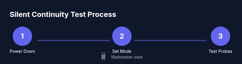
- 1
Power down
Turn off power to the circuit and disconnect power sources. If working on a car or device with capacitors, wait a moment for energy to dissipate and discharge any residual charge before touching components.
Tip: Double-check with a separate test lead that no voltage is present before touching conductors. - 2
Set meter to appropriate mode
Configure the meter to resistance (ohms) mode or the dedicated continuity setting if your model provides one. If beeper is a feature, disable it so you rely on the display readings instead.
Tip: Refer to the user manual for beep settings and range selection to avoid hidden readings. - 3
Connect probes to test points
Place the probes firmly on the two points you want to test. Use clips if the test area is small or awkward to hold.
Tip: Ensure good contact; shaky probes can produce fluctuating readings. - 4
Read and record resistance
Observe the displayed resistance. Note a very low reading or near-zero value as an indicator of continuity; note any open or high readings as potential faults.
Tip: If the reading is unstable, re-position the probes and re-test. - 5
Compare with a reference path
Test a known-good wire or path to establish a baseline. Compare the reading to your suspect path to decide if there’s a fault.
Tip: A consistent baseline makes it easier to judge ambiguous results. - 6
Test suspected faulty section
Isolate the section you suspect and retest. Check both ends of the suspected area to identify where the fault lies.
Tip: If it’s a loom, test along several adjacent wires to map the faulty segment. - 7
Mute the audible beep when needed
If your meter’s beep is loud or you’re working in a noise-sensitive area, turn off the beep and rely on resistance readings and the display.
Tip: Some meters allow quick beep toggling; locate the setting in the menu. - 8
Document results and plan next steps
Record the readings, paths tested, and any repairs or re-terminations you plan to perform. Use a simple diagram if helpful.
Tip: Include date, circuit name, and component location for future reference.
Your Questions Answered
Is it safe to test continuity on powered circuits?
No. Always disconnect power and discharge capacitors before testing continuity to avoid shocks or meter damage.
No. Always disconnect power and discharge capacitors.
What reading indicates good continuity?
A reading close to zero ohms generally indicates a good, continuous path. If the display shows OL or a high value, the path is open or broken.
A near-zero reading usually means continuity; OL or a high value means the path is open.
Why might there be no beep even when there is continuity?
Some meters mute the beep by default or require special settings. Rely on the resistance reading instead and verify mode is set to continuity or ohms.
The beep may be disabled or not configured; check the meter settings and rely on the display.
Can I use a known-good wire for comparison?
Yes. Test a known-good path first to establish a baseline, then compare with the suspect path to determine if there’s a fault.
Absolutely—use a good path as a baseline for comparison.
Is it safe to test automotive wiring with the car off?
Yes, as long as the car is off and the battery is disconnected. Follow standard safety practices when probing under the hood.
Car testing is fine when the vehicle is off and safe precautions are taken.
Watch Video
Key Takeaways
- Test with power off before touching any conductors.
- Low resistance generally means a continuous path.
- Use a known-good baseline for comparison.
- Document readings and plan next steps for repairs.