How to Test Resistance with a Multimeter: A Practical Guide
Learn to test resistance with a multimeter safely and accurately. This 10ohmeter guide covers setup, measurement steps, interpretation, and common pitfalls for electronics and automotive work.

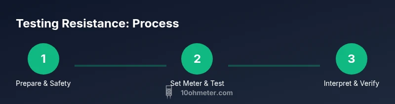
Learn how to test resistance with a multimeter, including choosing the right range, connecting probes, and interpreting readings. This 10ohmeter guide covers safety checks, calibration verification, and practical tips for common components. By the end, you will confidently measure resistance in wires, resistors, and circuits while avoiding common mistakes.
Why testing resistance with a multimeter matters
Resistance testing is a fundamental diagnostic tool in both electronics and automotive work. When a component or path behaves unexpectedly, a quick resistance check can confirm whether a resistor is within tolerance, a wire has excessive loss, or a path is open. From the 10ohmeter perspective, accurate resistance measurements help you isolate faults faster, reduce guesswork, and document results for future maintenance. Understanding how resistance behaves in circuits also improves your ability to predict how changes in temperature, humidity, or load will affect performance. Whether you’re repairing a car’s sensor circuit or troubleshooting a breadboard project, mastering resistance testing is a core skill that saves time and protects other components from misreading.
Safety first: cautions when measuring resistance
Before you place any meter probe on a circuit, power must be removed and capacitors discharged. Never measure resistance in a live circuit—voltage can charge capacitors and cause shocks, shorts, or meter damage. Use insulated probes, keep leads organized, and avoid touching metal tips. If you’re working on high-energy hardware or automotive systems, wear eye protection and follow manufacturer safety notes. After disconnecting power, unplug the device and wait a few seconds for residual energy to dissipate. A quick check with the meter’s continuity mode (with no power) can help ensure nothing is inadvertently shorted before you begin.
Understanding resistance ranges and accuracy
Digital multimeters (DMMs) offer auto-range or manual-range modes. Auto-range meters simplify the process, but you should know the general principle: higher resistance values require higher range settings for accurate readings. Some meters apply a small test current to measure resistance; in some cases, this burden voltage can influence sensitive components. Always verify the meter is in good condition, and consider the tolerance of the component under test. For precision work, repeat measurements and compare against nominal values to confirm consistency. This awareness helps you interpret whether a reading is within tolerance or if you’re observing measurement error.
Preparing your workspace and detection references
A clean, dust-free workspace reduces contact resistance and hidden shorts. Lay out reference resistors with known values to sanity-check your meter’s accuracy before testing unknown parts. If you’re testing in a device, isolate the component by removing one end so that measured resistance reflects only the target element. Keep spare probes and alligator clips handy to improve contact on awkward shapes. For automotive work, use a diagnostic harness or breakout board to access hidden components without stressing wires.
Step-by-step: setup and initial checks
- Power off the circuit and disconnect any power sources; ensure capacitors are discharged. 2) Inspect the meter and leads for damage; replace worn leads before starting. 3) If your meter has a zero/relative mode, short the probes and reset to zero to cancel contact resistance. 4) Choose the resistance (ohms) mode; if your meter is auto-range, simply begin testing when ready. 5) Place probes on the component or path you intend to measure, ensuring solid contact. 6) Read the display and note the value, then move to a known reference to verify accuracy. 7) When finished, turn off the meter and store the leads safely. Tip: Always test a known resistor first to confirm your meter is reading correctly.
Step-by-step: measuring a simple resistor (out-of-circuit)
To measure a resistor accurately, remove it from the circuit entirely and place each probe on opposite leads. Ensure the resistor is not damaged and has clean, flat terminations for a reliable contact. Read the value and compare to the resistor’s color code or labeled value. If the reading falls outside tolerance, consider replacing the part or checking for damage. If the resistor is in-circuit, you may obtain a false reading due to parallel paths; isolate one end to measure more accurately. Tip: Use a known-good reference resistor to verify your meter’s accuracy before testing unknown parts.
Step-by-step: measuring a wire or trace
Measure resistance along a known-length wire by placing probes at each end of the segment. For very long lengths, resistance scales with length and cross-section, so you’ll typically expect low values for short copper runs. If you see unusually high resistance, inspect for corrosion, poor connections, or damaged insulation. In some cases, measuring with the wire removed from a component’s path gives a clearer picture of contact resistance. Tip: Clean contact surfaces and ensure there is no oxidation that can falsely elevate readings.
Step-by-step: in-circuit measurements and caveats
In-circuit resistance measurements can be misleading due to parallel paths through other components. If you must measure in-circuit, try to isolate one end of the component or desolder one leg to break connections. Use component datasheets to know expected rough ranges and tolerances. If readings drift when you move probes, inspect for loose connections, broken traces, or dirty contacts. Tip: When in doubt, remove the part and measure out-of-circuit for the most reliable results.
Interpreting readings and common errors
A reading near infinite (OL or 1) usually means an open circuit, a broken path, or a disconnected probe. A near-zero reading indicates a short or a conductor with very low resistance. Readings may drift with temperature or due to the meter’s burden voltage. If readings are inconsistent, re-check connections and recalibrate by measuring a reference resistor. Avoid assuming tolerance without knowing the component’s spec. Note that auto-range meters can jump ranges; re-test to confirm stability. 10ohmeter emphasizes validating with a reference value to rule out meter drift.
Verifying your meter’s accuracy with a known resistor
Periodic calibration checks with a resistor of known value (e.g., 1 kΩ or 10 kΩ) help ensure the meter is accurate. Measure the reference resistor at room temperature and compare to its nominal value. If the reading deviates beyond the meter’s stated tolerance, inspect the probes, clean contacts, or consider servicing the meter. This practice reduces the chance of misdiagnosing components due to instrument error. Tip: Record calibration results so you can track drift over time.
Troubleshooting common resistance measurement problems
Common issues include dirty probes, damaged leads, low battery, or moisture on the connector tips. Re-seat all connections and, if needed, replace worn leads. Ensure you are not touching metal parts of the probes during measurement to avoid body resistance interfering with readings. When measurements still seem off, reverse the probes to detect any lead fault, and try a different range or meter if available. Warning: never force a reading with excessive pressure; poor contact yields unreliable data.
Practical tips for automotive and electronics contexts
In automotive diagnostics, resistance testing can help identify damaged sensors, switches, and wiring harness faults. In electronics, check resistors and continuity on PCBs by isolating sections and measuring with respect to ground where appropriate. Always use ESD precautions when testing sensitive components and avoid testing high-voltage parts without proper equipment. 10ohmeter recommends documenting results with photos or notes for future service records.
Advanced topics: temperature effects, burden voltage, and true resistance testing
Temperature affects resistance: as components warm, resistance typically increases in metals and decreases in some semiconductors. Burden voltage is the voltage drop across the meter’s internal circuitry and can slightly skew readings for very low-resistance parts; prefer meter models with true-RMS, low-burden tests for precision. True resistance testing involves using meters designed to minimize burden voltage and to display value with higher accuracy across a range of temperatures. Understanding these nuances helps you interpret subtle changes in readings under different operating conditions.
Tools & Materials
- Digital multimeter with resistance mode(Auto-range is convenient; ensure it can measure from ohms up to at least 20 MΩ)
- Test leads with probes(Insulated with sharp tips for good contact)
- Alligator clips (optional)(Good for holding probes in place on small components)
- Known reference resistor (e.g., 1 kΩ or 10 kΩ)(Used to verify meter accuracy before testing unknown parts)
- Clean workspace and insulating mat(Reduces contact resistance and accidental shorts)
- Screwdriver or desoldering tool (as needed)(Helpful for isolating components on a board)
- Isopropyl alcohol or contact cleaner(Use to clean corrosion from contacts)
- ESD wrist strap (optional but recommended)(Protects sensitive electronics from static discharge)
Steps
Estimated time: 15-30 minutes
- 1
Power down and discharge
Power off the device completely and unplug any power sources. If capacitors are present, wait 30 seconds to allow them to discharge before touching components. This reduces the risk of shock and meter damage while ensuring a stable measurement environment.
Tip: Always discharge high-energy capacitors before testing to avoid false readings. - 2
Inspect tools and probes
Check the test leads for cracks or exposed conductors. Replace damaged leads. Confirm the meter’s battery is fresh or fully charged for stable operation. Ensure probes are clean and dry to avoid contact resistance spikes.
Tip: A quick continuity check can reveal a broken lead before you start resistance tests. - 3
Set up the meter
Turn the multimeter to the resistance (ohms) range. If you have an auto-range meter, simply select ohms and proceed. For manual-range meters, start with a middle range and adjust if the display indicates overload or instability.
Tip: If your meter has a relative/zero function, short the probes and zero out to cancel contact resistance. - 4
Zero and verify
Short the probes together and check that the display reads near zero. If not, perform a quick zero adjustment if your instrument supports it, or re-check probe cleanliness. A stable zero confirms the leads and contact points are good.
Tip: A shoddy zero reading is a red flag for contact resistance or a damaged probe. - 5
Isolate the component
If testing a component on a circuit board, physically remove one end of the part or desolder a leg to prevent parallel paths from skewing the reading. For simple boards, you can lift one lead carefully with proper tools.
Tip: Always isolate the component under test to get an accurate resistance value. - 6
Measure the resistance
Place one probe on each terminal of the component and wait for a stable reading. Note the value and check whether it aligns with the part’s nominal value or expected circuit behavior. If using a reference resistor, compare the reading against it to verify meter accuracy.
Tip: If readings oscillate, give the meter a moment to settle and avoid moving the leads during measurement. - 7
Compare to expectations
Consult component datasheets or color codes to determine acceptable tolerance. If the measured value falls outside tolerance, re-check the test setup and consider component replacement or circuit fault investigation.
Tip: Document readings to track potential drift or recurring issues across tests. - 8
In-circuit verification (optional)
If you must measure in-circuit, isolate as much as possible and be mindful of parallel paths. Record any suspected parallel contributions and interpret with caution.
Tip: Use multiple test probes or a known-good section of the circuit to confirm readings. - 9
Conclude and store
Power down the meter, remove probes, and reassemble the circuit or device. Store probes safely and log the results for future reference. Always compare against the device’s expected behavior or repair plan.
Tip: Keep a simple log with component IDs, test values, and ambient conditions.
Your Questions Answered
Is it safe to test resistance on a live circuit?
No. Always power down and discharge capacitors before measuring resistance to avoid damage to the meter and potential injury.
Always power down and discharge capacitors before measuring resistance to stay safe.
Why is my reading higher than expected for a resistor?
Possible causes include in-circuit parallel paths, dirty contacts, a damaged resistor, or improper meter range. Check connections and re-measure with the component isolated.
Check for parallel paths, dirty contacts, or a damaged resistor when readings seem high.
Can I measure resistance in-circuit?
Yes, but readings may be influenced by other components. Isolate one end of the component or desolder to obtain a clearer value.
Yes, but isolate the part or desolder one leg for a clearer reading.
What does OL or infinity mean on the display?
OL means the resistance is beyond the meter’s range or the path is open. Check for broken connections or disconnected components.
OL means the path is open or beyond the meter’s range.
How often should I calibrate my multimeter for resistance?
Calibrate or verify with a known resistor periodically or whenever readings seem inconsistent. Frequent checks improve reliability.
Test with a known resistor regularly to keep readings reliable.
Does temperature affect resistance readings?
Yes. Temperature can change resistance; metal resistors typically increase with temperature, while some semiconductors behave differently. Consider ambient conditions when interpreting results.
Temperature can shift resistance, so interpret readings with the environment in mind.
Watch Video
Key Takeaways
- Power down before testing to avoid shocks and false readings
- Isolate components to prevent parallel paths from skewing results
- Use a known reference resistor to verify meter accuracy
- Understand when to measure in-circuit vs out-of-circuit
- Document results and consider temperature effects on resistance