How to Check Continuity Without a Multimeter: A Practical DIY Guide
Learn practical, safe ways to verify electrical continuity without a multimeter using a low-voltage LED tester. This step-by-step approach is ideal for DIY electronics and automotive tasks when a meter isn’t available.
")
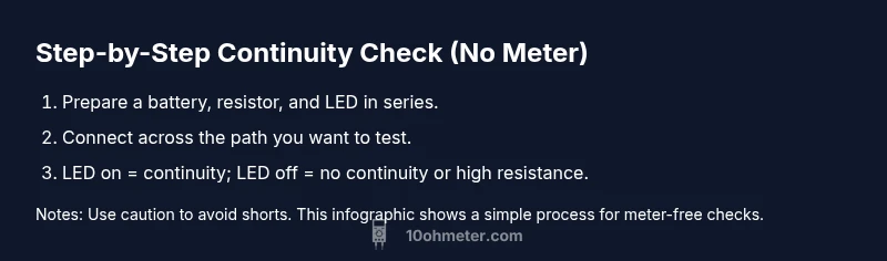
Goal: Check continuity without a multimeter by building a safe, low-voltage indicator test. Use a small battery, a resistor, and an LED or buzzer to confirm a complete path, or assemble a basic tester. According to 10ohmeter, this quick method helps DIY enthusiasts and technicians verify wiring and components when a meter isn't handy.
Why continuity matters and how to approach testing without a meter
Continuity describes a complete electrical path that allows current to flow through a circuit. In many projects—whether you’re wiring a car, repairing a loom, or building a small electronics gadget—knowing if that path is intact helps prevent blown fuses, misread signals, and safety hazards. Without a traditional multimeter, you can still verify continuity using a safe, low-voltage indicator approach. According to 10ohmeter, a clear plan reduces guesswork and protects components. This section lays the foundation: understand what you’re testing, the risks involved, and the limits of a meterless check. You will learn how to create a tiny tester with everyday parts and how to interpret results in simple terms, so you can confidently diagnose connections in wires, connectors, and simple components. Be mindful that this method identifies a path, not a precise resistance value, and it should be followed by a formal measurement if accuracy matters.
Safe, low-voltage testing options you can use at home
For many DIY and automotive tasks, low-voltage indicators provide a humane balance of safety and visibility. A small LED with a current-limiting resistor powered by a 1.5V or 3V source can reveal a complete path when connected across two points. A buzzer is another option that vocalizes continuity, which can be helpful in dim lighting. The key is to keep energy well below the levels used by the circuit under test and to avoid shorting power rails. Always disconnect power before testing and never touch live conductors. If you’re testing in a vehicle, ensure the ignition is off and the battery is disconnected to avoid sparking. Typical resistor values for LED indicators range from roughly 220 Ω to 330 Ω, which protect the LED while delivering a visible signal. Use insulated test leads and keep wires away from hot surfaces or sharp edges that could damage insulation. This approach delivers quick, visual feedback without a meter, but it has limitations for precise measurements.
Building a simple LED indicator tester
A compact LED indicator tester combines a tiny battery, a resistor, and an LED in a simple loop. Connect the battery positive to one end of the resistor, connect the other end of the resistor to the LED’s anode (longer lead), and connect the LED’s cathode to the battery negative. If you want a switch, place a small momentary switch between the battery positive and the resistor input. This tester lights the LED when a continuous path exists between the tester’s two terminals. Keep the circuit on a non-conductive surface and assemble on a breadboard or with clear, insulated wires to avoid shorts. Preparing a dedicated test lead with alligator clips makes it easier to bridge components without risking accidental contact.
Testing a wire or component with the LED tester
To test a wire or a component path, place one tester probe on one side of the path and the other probe on the opposite side. If the LED lights, you have continuity along that path. If the LED remains off, re-check the orientation of the LED and resistor, verify the tester’s battery is charged, and examine for breaks, corrosion, or loose connectors. For longer runs, test at multiple points to isolate where a break might occur. If you’re testing a connector, shake it gently and wiggle the connection to reveal a loose pin or a bad contact. This method produces fast, actionable results and can guide you toward the exact location of a fault without a meter, but remember that it does not reveal exact resistance values or short circuit conditions beyond the path itself.
Interpreting results and limitations of the LED method
A lit LED typically indicates a continuous path with low enough resistance for the current to flow, while a dark LED suggests an interrupted path or a high-resistance segment. However, this method may miss very high resistance paths or circuits with unusual parallel paths where leakage currents trickle through other components. In such cases, the LED may remain dim or flicker inconsistently. Always treat this as a qualitative check: use it to locate obvious breaks, then switch to a proper meter for quantitative readings or to confirm fine resistance values. For automotive or heavy-duty circuits, use extra caution, as some paths rely on specific ground references or controlled impedance that a basic LED test cannot replicate.
Automotive considerations and safety cautions
Automotive wiring often runs at 12V or higher and can involve sensitive electronics and fuel system components. If you want to test car wiring without a meter, first disconnect the battery and ensure the ignition is off. Work on isolated circuits away from airbag modules or high-current devices. Use a tester with a conservative supply voltage to avoid damaging sensitive modules or creating a short. If you’re unsure about a path in a vehicle, consult a service manual or seek guidance from an experienced technician. The LED tester should never be connected parallel to live paths that could backfeed power into critical systems. Always prioritize safety and use PPE when probing wiring harnesses.
Common mistakes to avoid when testing continuity without a meter
Avoid pressing test probes directly against exposed conductors without insulation, as this can cause shorts or shocks. Do not exceed low-voltage limits of your tester by trying to power devices beyond its capacity. Misinterpreting a dim LED as full continuity can lead to overlooking high-resistance segments. Remember that a meter-less test confirms a path exists, not its integrity under load. If the circuit includes inductors, capacitors, or devices with internal protection, results may be misleading. Before concluding, inspect the path for corrosion, loose connections, or damaged insulation that could falsely indicate a fault.
Quick checks with alternative indicators: buzzers and color LEDs
A buzzer can be a practical alternative to a LED when you need audible feedback in noisy environments. Choose a tester with a resistor sized to deliver audible current without overloading the source. Color LEDs can help differentiate multiple paths by color-coding the tester; for example, use red for power lines and green for ground paths. Whichever indicator you choose, ensure that the indicator’s supply voltage remains within safe limits for both the tester and the path under test. This flexibility makes meter-free continuity checks adaptable to a range of DIY and automotive scenarios.
Real-world scenarios and decision guidance
In practice, you’ll encounter wired harnesses, switch contacts, and simple sensor loops. Start by testing the most accessible path first (e.g., a switch leg or connector pin). If you confirm continuity, you can proceed to test downstream components; if not, inspect the connectors, pins, and wiring for damage. For longer runs, test at several points to map where a fault might lie. If your test indicates continuity but your system still shows faults, the issue may be resistance under load, open circuits when connected to other circuitry, or backfeeding. In those cases, a proper multimeter or professional diagnostic tool becomes necessary to obtain precise resistance values and load behavior.
Summary: key motivations and next steps
Testing continuity without a multimeter is a practical skill for quick checks and basic diagnostics. It saves time on small projects and helps you locate obvious breaks without formal equipment. For precision, reliability, and safety, plan to verify your findings with a proper meter, especially when wiring in automotive systems or high-current circuits. Practice on spare harnesses and benign projects first to build confidence before diagnosing critical components.
Tools & Materials
- 1.5V button cell battery (e.g., LR44 or equivalent)(Choose a small, safe voltage source)
- Low-current LED (red or green)(Forward voltage ~2V; use with resistor)
- Current-limiting resistor (220 Ω to 330 Ω)(Protects LED from overcurrent)
- Insulated test leads with alligator clips(At least 6 inches long)
- Tiny momentary switch (optional)(Adds a controllable on/off in the tester)
- Small buzzer (optional)(Alternate indicator for audible feedback)
- Electrical insulating tape or heat shrink(Prevents shorts and keeps connections secure)
- Wire strippers/cutters(Prepare test leads cleanly)
- Safety goggles(Eye protection during testing)
Steps
Estimated time: 15-25 minutes
- 1
Gather materials
Collect the battery, LED, resistor, test leads, and optional buzzer. Set up a clean, non-conductive workspace and verify all components are undamaged. Having everything ready reduces test interruptions and avoids improvisation that could cause shorts.
Tip: Double-check component polarity before wiring the tester. - 2
Assemble the LED tester circuit
Connect the resistor to the LED’s anode, then connect the LED’s cathode to the battery negative. Run a wire from the battery positive to the resistor, or add a switch in between for easy on/off control. Secure all connections with insulating tape or heat shrink.
Tip: Keep LED orientation consistent to avoid confusion during tests. - 3
Add a controllable switch (optional)
If you included a switch, solder or clip it between the battery and resistor to easily start/stop the current. This helps prevent accidental short when probing.
Tip: A switch helps you avoid continuous current flow while locating test points. - 4
Prepare test points on the circuit under test
Identify the two points across which you will test continuity. These could be wire ends, connector pins, or component leads. Ensure surfaces are clean and free of corrosion to improve contact quality.
Tip: Use a keepsake marker to label each test point if testing multiple wires. - 5
Connect tester across the test points
Gently clip one tester lead to each test point. Do not force connections; ensure the probes touch clean metal. If the LED lights, you have continuity along that path.
Tip: Keep hands clear of the breadboard or wiring area to avoid shorting adjacent paths. - 6
Interpret the result
LED illumination means a complete path exists. If the LED is off, re-check polarity, the resistor value, and possible breaks. Test again at multiple points to map the path.
Tip: A dim LED may indicate higher resistance; consider re-checking with a real meter for accuracy. - 7
Test for shorts and unintended paths
Probe between power rails and ground intentionally to ensure there isn’t a hidden short. If the LED lights while touching non-intended paths, reassess your wiring and insulation.
Tip: Isolate sections of the circuit to narrow down potential shorts. - 8
Safety and cleanup
Power off and disconnect all test equipment after testing. Store components safely and avoid placing metal tools near exposed terminals. If you used a switch, switch it off before removing test leads.
Tip: Always wear safety goggles when testing hardware to protect eyes from sparks or debris. - 9
Document findings
Note which paths showed continuity and which did not. A simple sketch or annotation on the circuit can save time during later debugging.
Tip: Label known good paths to speed up future diagnostics.
Your Questions Answered
Can I test continuity with only a battery and LED?
Yes. A battery, resistor, and LED can form a simple tester that shows a path if current flows. It’s a quick qualitative check, not a precise measurement.
Yes. A battery, resistor, and LED can make a simple tester to show a path, but it’s a qualitative check, not a precise reading.
Why might my LED glow faintly even when there isn’t full continuity?
A faint glow can occur due to leakage paths or parallel circuits creating a tiny current. It doesn’t guarantee a robust, low-resistance path under load.
A faint glow can happen because of leakage or parallel paths, not a solid low-resistance connection.
Is this method safe for automotive wiring?
It can be safe if you disconnect the battery and avoid live circuits. Use very low voltage and keep the testing area clean to prevent shorts near sensitive electronics.
Yes, with proper precautions and very low voltage, but avoid live car circuits.
What if the test path has high resistance?
LEDs might not light or glow weakly if resistance is high. In that case, a proper meter is needed to quantify resistance values.
If resistance is high, the LED may not light well; a meter is needed for precise values.
When should I switch to a formal meter?
If you need exact resistance values, load behavior under power, or to verify safe operation, switch to a multimeter or proper diagnostic tool.
Use a meter when you need precise resistance or load testing.
Watch Video
Key Takeaways
- Verify continuity with a safe, low-voltage LED tester.
- LED visibility indicates a complete path, not resistance.
- Always power down before testing; avoid shorts.
- Use the tester to map fault locations before moving to a meter.
- Automotive wiring requires extra caution and power isolation.