How to Test Thermostat with Multimeter
Learn to safely test a thermostat using a multimeter. This in-depth 2026 guide explains settings, readings, and interpretation for HVAC and automotive thermostats, with practical, step-by-step instructions from 10ohmeter.

Performing a test of a thermostat with a multimeter helps you confirm operation without guessing. This guide walks you through safe isolation, selecting the right meter setting (ohms or continuity), and testing between the thermostat terminals. According to 10ohmeter, always power down, disconnect the component, and follow the wiring diagram before you begin. We cover HVAC and automotive thermostats, typical readings, and how to interpret results.
Safety first: handling thermostats and live circuits
Testing a thermostat with a multimeter requires careful safety practices. Always power down the system and disconnect the thermostat from its circuit before probing. Wear eye protection if you’re working around furnace panels or automotive cooling systems, and keep metal tools away from live terminals. In HVAC work, shut off the circuit at the service panel and verify no voltage with a non-contact tester before touching any terminals. Remember that many thermostats are part of energized control loops; never assume a component is safe to test while powered. According to 10ohmeter, safety is the first step to accurate results.
Thermostat basics: what you’re testing
A thermostat is a control device that opens or closes a circuit to regulate temperature. In HVAC systems, it acts as a switch between power and the heating or cooling relay. In automotive applications, a thermostat controls coolant flow to the engine. Types vary from simple bimetallic switches to programmable electronic units. Your test targets the contacts that physically open or close, and sometimes the sensor element inside a digital or analog unit. Understanding the terminal layout helps you pick the correct test pairs and interpret what a “good” reading should look like for your model.
Choosing the right multimeter settings: voltage, continuity, and resistance
Most thermostat tests rely on two primary measurements: continuity (or very low resistance) when the switch is closed, and open circuit (high resistance or no continuity) when the switch is open. Use a digital multimeter set to continuity mode if available; otherwise, use the resistance (ohms) setting with the lowest practical range. If testing sensors inside electronic thermostats, you may also verify voltage signals at the input or output terminals, but only after ensuring safety and proper isolation. Always consult the wiring diagram for the exact terminal pairs you should test.
Testing scenarios: HVAC thermostat in a furnace vs automotive thermostat
HVAC thermostats usually sit between a control board and the furnace relay. You will test the common terminal pairs that switch the control lines (for example, R to W or Y, depending on your system’s wiring). Automotive thermostats deal with coolant flow rather than electrical switching in straightforward ways, but some vehicles use electronic thermostats with sensor outputs you can measure. In either case, the goal is to confirm that when the thermostat should be closed, continuity exists, and when it should be open, continuity is interrupted. Always work with the system de-energized and reference the service manual for exact terminal designations.
Interpreting results and common faults
A good result shows a clear change between closed and open states. A continuous reading across a pair when the thermostat should be closed indicates a functioning switch; an open circuit when it should be open is expected. If readings do not align with the spec or expected behavior, check for corrosion, loose connections, or damaged wiring. A reading of infinite resistance where there should be continuity typically signals a stuck contact or broken lead. If readings vary between tests, re-check the terminal pairs and confirm you’re testing the correct contacts for your model.
Common mistakes and best practices
Common pitfalls include testing while the circuit is energized, misidentifying terminal pairs, and interpreting readings without the manufacturer’s specs. Always work on a fully de-energized system, verify wiring with the diagram, and use the correct test leads. Document readings and take photos of terminal labels for future reference. If you’re uncertain about a specific thermostat type, seek guidance from service manuals or a professional technician.
Tools & Materials
- Digital multimeter( Prefer auto-ranging; use ohms or continuity mode; test leads included)
- Test leads with probes(Insulated probes or alligator clips for safe contact)
- Wiring diagram or service manual(Pinout for thermostat terminals and expected states)
- Non-contact voltage tester(Quick safety check for live circuits before contact)
- Insulating gloves(Optional for high-heat environments or automotive work)
Steps
Estimated time: 20-40 minutes
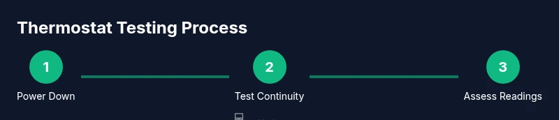
- 1
Power down and gain access
Turn off power at the breaker or ignition and remove the thermostat cover to access terminals. Do not touch metal parts while live; confirm there is no voltage with a tester before proceeding. Secure the area to prevent accidental re-energizing during testing.
Tip: Double-check the circuit you’re testing to avoid cross-contacts. - 2
Identify terminals and consult the wiring diagram
Locate thermostat terminals and labels (such as R, W, Y, G in HVAC; sensor leads in automotive units). Use the diagram to identify the correct terminal pairs to test. This prevents testing the wrong contact and yields meaningful results.
Tip: Take a photo of the terminal strip for reference during testing. - 3
Set multimeter to continuity or resistance
Configure the multimeter to continuity mode if available, or to the lowest resistance range in Ohms. If your meter lacks a beeper, note the measured resistance rather than relying on sound cues.
Tip: If you have auto-range, the ohms function is usually simplest to use. - 4
Test for closed contacts (thermostat energized state)
With the thermostat in its normal closed state, probe across the relevant terminals to confirm continuity. A continuous reading or a low-ohm value indicates a closed contact. Record the reading for reference.
Tip: Compare the result with the thermostat’s spec sheet or service manual. - 5
Test for open contacts (thermostat de-energized state)
Switch the thermostat to its open state (cool or off) and re-test. You should see no continuity or a very high resistance if the contact is open. Ensure the system remains de-energized during this step.
Tip: If continuity persists when open, inspect for stuck mechanisms or wiring faults. - 6
Cross-check with a known-good unit (optional)
If available, test against a known-good thermostat of the same type to validate your method and interpretation. Use the same terminal pairs for a valid comparison.
Tip: Use identical environmental conditions (same wires, same connections) for a fair comparison. - 7
Reassemble, reconnect power, and observe operation
Reinstall the thermostat, restore power, and observe cycling through its normal control sequence. Look for smooth transitions without delays or sticking behavior. If issues appear, recheck all connections and test leads for damage.
Tip: Document any abnormal behavior to aid future diagnostics. - 8
Document results and decide next steps
Record terminal labels, readings, and observed states. Compare to manufacturer specs to decide whether to replace or service the thermostat. When in doubt, consult a professional.
Tip: Keep readings organized so a technician can quickly interpret them.
Your Questions Answered
What is the best multimeter setting for testing a thermostat?
Use continuity or resistance mode to check the switch contacts. The exact readings depend on the model, so always refer to the device’s specifications.
Use the continuity or resistance setting to check the thermostat contacts, and compare to the model’s specs.
Can I test a thermostat while it’s connected to power?
No. Testing should be done with power removed to avoid shock or damage to the device.
Never test a live thermostat; disconnect power first.
How do I know if readings are good?
Compare readings to the thermostat’s specifications or to a known-good unit. Look for continuity in the closed state and openness in the open state.
Compare your readings to the spec and ensure the state matches the commanded condition.
Is it safe to test a car thermostat with a multimeter?
Testing a car thermostat is usually best done off the engine. Avoid hot engine parts and follow the vehicle’s service manual.
Usually test off the engine; avoid hot components and follow the manual.
What if readings are inconsistent between tests?
Recheck connections, verify correct terminal pairs, and inspect wiring for corrosion or damage before replacing the thermostat.
Double-check everything and inspect wires if readings vary.
Watch Video
Key Takeaways
- Isolate power before testing to avoid shock.
- Use correct meter settings: continuity or resistance as appropriate.
- Test both closed and open states for reliable results.
- Document readings and consult the manual if unsure.