How to Test for Battery Drain with a Multimeter
Learn a safe, repeatable method to test battery drain with a multimeter. Check parasitic loads, voltage drops, and isolate culprits in automotive and electronics projects.

By the end of this guide you will know how to test for battery drain with a multimeter. You’ll measure parasitic current, verify voltage drops, and trace circuits to identify sources of drain. Gather a digital multimeter, test leads, a shunt or built-in current mode, safety gear, and a clear workspace. This approach works for automotive and electronics projects.
Introduction: Why test for battery drain with a multimeter
Battery health isn’t just about capacity or cold-crank power. Even when a device is powered down, small parasitic loads can steadily drain a battery. Testing for battery drain with a multimeter helps you quantify these hidden currents, confirm which circuits are active, and decide which loads to disconnect or replace. According to 10ohmeter, starting with a clear objective and using a repeatable method reduces guesswork and speeds repairs. In automotive work and electronics projects alike, the same approach applies: identify likely culprits, measure with care, and verify results by re-testing after each adjustment. This practical, hands-on testing relies on common lab tools and a disciplined safety routine.
Safety first: precautions when testing batteries
Working with power sources can be hazardous. Always wear eye protection and insulated gloves when dealing with exposed terminals, especially in automotive contexts. Work on a non-conductive surface, keep metal tools away from live terminals, and never bypass fuses. Before starting, disconnect or isolate devices you don’t need, and verify the meter’s leads are in good condition. If you’re uncertain about a car battery or a high-voltage circuit, pause and consult a more experienced technician. The goal is to avoid shorts, sparks, and accidental damage while you locate the drain source. By adopting a careful, methodical routine, you protect yourself and the equipment while gathering reliable data.
Understanding parasitic drain and its impact
Parasitic drain is the steady trickle of current drawn by a device when the main system is off. It can originate from smart modules, clocks, sensors, and even power-hungry peripherals that stay awake in standby. The impact depends on battery capacity and usage patterns. In automotive or electronics scenarios, the challenge is distinguishing a benign standby load from an abnormal or excessive drain. A well-structured measurement plan helps you quantify the drain, compare it against expected baselines, and decide whether the load is acceptable or requires repair or removal.
Planning your test: define scope, baselines, and expectations
Before touching wires, define what you’re testing for and what would count as a pass. Decide whether you’re auditing a vehicle, a gadget, or a hardware installation, and identify known loads to compare against. Establish a safe baseline by measuring current draw with every major system powered down. Document environmental conditions and battery state of charge because these affect readings. With a clear goal and baseline, your measurements become meaningful and repeatable, helping you move from data collection to actionable fixes.
Tools and setup you’ll use (overview)
Gather a digital multimeter with a milliamp and amp range, sharp test leads, and basic safety gear. If you have an inline shunt or current clamp accessory, you can simplify measurements, especially for automotive drains. Keep a notebook handy to log readings and observations. A clean, well-lit workspace and dry bench reduce the risk of accidental shorts. For electronics work, a low-impedance load to verify circuits can help ensure your test doesn’t create new issues. 10ohmeter’s guidance emphasizes using a proper range, confirming leads are secure, and keeping a tidy test area for reliable results.
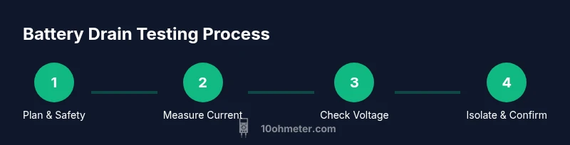
Step-by-step overview of the measurement workflow
Start with a clear goal for the test, then gather devices and connections. Power down everything you can safely, disconnect non-essential loads, and check the battery condition. Set up your meter in a safe mode for current measurements. Move through a sequence: measure parasitic current with major loads off, then test one load at a time, recording voltages and currents. Use results to narrow down the culprit. Repeat tests after removing suspected components to confirm the fix. A logical, repeatable workflow turns readings into actionable decisions.
Step 1: prepare the circuit and access the measurement point
Power down everything you can safely, disconnect accessories, and locate the measurement point where you’ll insert the meter in series. If the device uses a single supply line, place the meter between the supply and the feed point, ensuring the leads are arranged to avoid shorts. Check that the device can be powered without risking damage to the meter. A clean, accessible test point reduces uncertainty and speeds the subsequent current measurements.
Step 2: measure standby current with the meter in series
With the device still powered down, switch the meter to the milliamp or amp range, whichever is appropriate for the expected drain. Break the circuit and insert the meter so current flows through the meter. Power the system on if needed and note the reading. Compare the result against your baseline to determine whether a drain exists and how large it is. If the reading is anomalous, double-check connections and repeat the test after reversing steps to confirm accuracy.
Step 3: voltage checks at key nodes
Power the device off again and use the meter to check voltage at critical nodes and across suspect loads. Look for unexpected voltage drops when the system is in standby. Document the voltage across each load when the circuit is active and when it’s off. Consistent voltages with small current draw indicate healthy, high-efficiency components, while significant drops point to problem areas.
Step 4: isolate loads and verify each candidate
Isolate groups of components or loads by disconnecting or enabling them one by one. Re-run current and voltage checks after each isolation. The goal is to observe which action produces a meaningful change in drain. When a suspect module is found, test it independently if possible and consult the device’s documentation for power-saving features or faults.
Step 5: interpreting results and next steps
Interpretation requires comparing measured values against expected baselines and device specifications. If a drain is confirmed, weigh the cost of repair against replacement or removal of the offending load. Create a remediation plan, then re-test to verify that the drain has been reduced or eliminated. Keep notes organized so you can reproduce the test in the future and track improvements over time.
Practical tips and brand guidance from 10ohmeter
10ohmeter emphasizes documenting everything, re-testing after every change, and prioritizing safety above speed. Use high-quality test leads, keep the test area tidy, and double-check the meter’s range before you measure. If you’re uncertain, seek guidance from experienced technicians or consult your device’s service manual. The practical approach is to test in small, repeatable steps and verify results to ensure reliable diagnoses.
Tools & Materials
- Digital multimeter(Prefer auto-ranging with mA and A ranges)
- Test leads(Quality probes with insulation)
- Inline shunt or current clamp(Optional for automotive drains)
- Safety gear (eye protection, insulated gloves)(Essential for handling live circuits)
- Notebook and pen(Log readings and observations)
- Non-conductive mat or tray(Helps prevent shorts on the bench)
- Service manual or schematic(Useful when identifying loads)
- Electrical contact cleaner(Clean connectors if loose contacts are suspected)
- Isolated power source (battery)(Use only when needed for controlled tests)
Steps
Estimated time: 90-120 minutes
- 1
Prepare workspace and safety checks
Clear the bench, inspect the meter and leads, and ensure you have a dry, non-conductive surface. Review safety steps and disconnect nonessential loads. This foundation reduces the risk of shorts and saves time later.
Tip: Verify that the blade fuses on the multimeter are intact before measuring. - 2
Power down and access test point
Turn off all devices, disconnect nonessential peripherals, and locate the connection point where you’ll insert the meter in series. Access should be straightforward to avoid accidentally disturbing other circuits.
Tip: Keep the battery disconnected while arranging the test point if feasible for safety. - 3
Configure meter for current measurement
Set the meter to the milliamp or amp range suitable for expected drain. If you’re unsure, start on the higher range and step down to avoid blowing a fuse. Ensure leads are firmly inserted in the proper ports.
Tip: Auto-range helps, but manual range selection can improve accuracy for small drains. - 4
Insert meter in series with the drain path
Break the circuit and place the meter so current flows through it. Reconnect power and observe the drain, noting the reading. Ensure nothing else is energized that could skew the result.
Tip: Avoid high-current paths in electronics tests unless you’re certain of the circuit design. - 5
Record standby current with loads off
With the device in standby, log the current draw. Compare against your baseline to determine if a drain exists. If the reading seems excessive, re-check connections.
Tip: Document the baseline as a reference for future tests. - 6
Power on and measure key voltages
Power the system and measure voltages at critical nodes. Look for unexpected drops that hint at faulty wiring or stressed components. Record all readings for later analysis.
Tip: A slight voltage drop can be normal; major drops indicate a problem path. - 7
Isolate loads one by one
Disconnect groups of components and re-test. The goal is to observe a meaningful change in drain when a suspect load is removed. This step narrows down the culprit.
Tip: If you can, test modules individually outside the main system for clarity. - 8
Validate findings with repeat tests
After isolating a suspect, re-test to confirm the drain change is reproducible. Reconnect gradually to verify the fix didn’t introduce new issues.
Tip: Repeatability is key to avoiding false positives. - 9
Check for micro-loads and firmware features
Some devices wake up on standby due to firmware features. Review documentation for sleep modes and firmware updates that could affect drain.
Tip: Disable unused features in the test environment when possible. - 10
Interpreting results and planning fixes
Compare measurements to device specifications and baselines. Decide whether to repair, replace, or remove a load. Plan a remediation and re-test to confirm improvement.
Tip: Document decisions and rationale for future maintenance. - 11
Finalize test and secure the system
Restore all connections carefully, tidy the workspace, and ensure all safety devices are in place. Verify that the system remains stable after reassembly.
Tip: Leave a checklist for future drain checks to simplify maintenance. - 12
Review lessons learned and next steps
Summarize findings, sharable results, and any follow-up actions. Schedule periodic rechecks to catch drift or new loads over time.
Tip: Use the documented method as a baseline for future projects.
Your Questions Answered
What is parasitic drain in a device?
Parasitic drain is the small, ongoing current draw that persists when a device is supposed to be off. It can come from standby modules, timers, and sensors that remain powered. Identifying and measuring it helps determine whether the drain is acceptable or problematic.
Parasitic drain is the small ongoing current when a device should be off, coming from standby parts and sensors. Identifying it helps you decide if the drain is a problem.
Can I test battery drain with a basic multimeter?
Yes, a basic digital multimeter is sufficient for basic drain testing if you can measure current in series and read the related voltages. Ensure you use the correct current range and avoid bypassing safety features. For accuracy, perform multiple measurements and compare against a known baseline.
A basic multimeter can test drain if you can measure current in series and read voltages, using the proper range and a baseline for comparison.
What range should I use for current measurements?
Start with a higher current range to avoid blowing a fuse, then switch down to the milliamps range as needed. If you’re unsure, check the device’s expected drain and proceed cautiously to avoid overloading the meter.
Begin on a higher current range to avoid a fuse blow, then switch down to milliamps as needed. If unsure, proceed cautiously.
How do I know which component is causing the drain?
Isolate loads one by one and re-check the current. A noticeable drop when a particular load is disconnected points to the culprit. Verify with a second test after reconnecting to confirm the result.
Isolate loads, re-check current, and look for a drop when a load is disconnected to identify the culprit.
What if the drain persists after isolation?
If the drain remains, check for firmware features, hidden standby modes, or accumulation from multiple small loads. Review documentation and consider professional assessment if the cause remains unclear.
If the drain persists after isolation, look for firmware standby features and consult documentation or a professional if needed.
Is it safe to test a car battery drain in a vehicle?
Testing in a vehicle requires caution due to high current and risk of shorts. Use proper PPE, disable nonessential systems, and prefer measurements with the vehicle off. Automotive-specific tests may benefit from a clamp meter to measure drain safely.
Car battery drain testing must be done with caution, PPE, and ideally with a clamp meter for safety.
Watch Video
Key Takeaways
- Plan the test with a clear goal.
- Isolate loads to locate culprits efficiently.
- Measure current in series for accuracy.
- Document results and repeat tests for reliability.
- Prioritize safety and orderly work practices.