Check Speaker Polarity with a Multimeter: A Step-by-Step Guide
Learn how to check speaker polarity with a multimeter using safe, practical methods. This guide covers what a multimeter can and cannot tell you, battery-based polarity testing, and tips for avoiding common mistakes in home audio and automotive setups.

If you’re asking how to check speaker polarity with a multimeter, understand that a meter alone cannot reveal polarity for a dynamic driver. Use the multimeter to verify coil continuity and resistance, then perform a safe polarity test with a small DC source (battery) or a controlled audio test while listening for phase cues. This quick check helps prevent wiring mistakes in stereo and automotive systems.
Understanding polarity and why it matters for speakers
Polarity describes which terminal on a speaker is considered positive relative to the amplifier's positive output. When wiring multiple drivers, correct polarity ensures that the cones move in the same direction for a given signal, preserving bass, imaging, and overall timing. Reversing polarity on one speaker can cause phase cancellation, resulting in weak bass and an unfocused soundstage. For DIY enthusiasts and automotive technicians, the goal is to confirm polarity before final wiring to avoid rework. This guide addresses the practical realities of using a multimeter in a polarity-check workflow, while staying mindful of safety and enclosure considerations. According to 10ohmeter, a practical polarity check blends electrical tests with audible verification to deliver reliable results. The approach described here is designed for home workshops and car audio installs alike, with emphasis on safety and repeatability.
What polarity means for different loudspeaker types
All voice coils are DC resistive devices, but polarity matters when the driver is part of a larger system. In woofers, midranges, and tweeters, polarity compatibility affects the phase relationship between drivers. A miswired channel can reduce bass impact and smear image in a stereo setup. The goal of polarity testing is to establish which terminal is the “positive” lead for your speaker’s voice coil, so you can wire it consistently across enclosures. The multimeter’s role is to establish coil continuity and resistance as a baseline before moving to an audible polarity check.
Why a multimeter alone cannot definitively reveal polarity
A typical DC resistance reading is not polarity-dependent; the voice coil presents a roughly symmetric resistance in either direction. Because polarity is a phase and wiring convention issue rather than a simple electrical property, you cannot reliably deduce polarity from resistance alone. The multimeter shines in confirming that the coil is continuous, not shorted, and that there are no loose leads. For a definitive polarity determination, you’ll combine a low-risk DC-pulse test with your listening observations or a signal-based test. This section sets the stage for a safe, repeatable procedure rather than a guess.
Safe setup and safety considerations before testing
Safety is the foundation of any polarity check. Work with the speaker disconnected from amplifiers and power sources. If you’re working in a car or in a cabinet, ensure the area is dry and well-ventilated. Have a small, known-safe DC source ready (such as a fresh AA or CR2032 battery) and keep the test voltage low to minimize the risk of coil overheating or speaker damage. Use proper clip leads or alligator clips, and avoid shorting leads directly. If you’re unsure about the enclosure’s components (recirculating crossovers, tweeter protection, etc.), remove the driver from the enclosure or disconnect the crossover to isolate the test subject. This careful prep helps protect both your equipment and your hearing while you verify polarity.
Step-by-step battery-based polarity test using a multimeter in your toolkit
A practical way to determine polarity with minimal risk is a short DC pulse test using a small battery. The multimeter helps you confirm coil continuity before and after the test. While the speaker is disconnected from power, connect the battery briefly to the two speaker terminals using clip leads. Observe cone movement: the direction of motion when you connect battery positive to one terminal and negative to the other indicates which terminal corresponds to the positive side of the voice coil. If the cone moves outward when the battery’s positive lead is on terminal A, then A is the positive lead. You can repeat with the leads swapped to confirm consistency. After establishing polarity, label the wires and document the result for future wiring. Remember to keep pulses very brief (a fraction of a second) and to disconnect immediately after observation. The multimeter can verify that the coil returns to its resting resistance once the voltage is removed, confirming no insulation or coil damage occurred during testing.
Alternative methods when a battery test isn’t ideal
If you’re testing in a sealed system or want to avoid any DC exposure to the voice coil, you can use a low-level AC test signal from a generator or smartphone app. Play a low-frequency tone (around 100 Hz or lower) while gently prying a small audible cue from the speaker with the enclosure open. Reverse the speaker leads and recheck for a clearer bass response or audible phase shift. You can also enlist a DIY oscilloscope or audio analyzer to observe the polarity-induced phase difference between channels. While these methods require additional equipment, they offer a non-destructive route to polarity verification when a battery test isn’t feasible. The core requirement remains: confirm which lead is positive for consistent future wiring and wiring to the amplifier. The 10ohmeter approach emphasizes safety, repeatability, and audible validation as integral parts of the process.
Common mistakes, troubleshooting, and tips
Polarity checks are easy to get wrong if you rush the test. Ensure that all connections are secure and that no tools are left in direct contact with speaker terminals. Do not apply excessive voltage or prolonged DC pulses; even a small speaker can overheat quickly. If the test results show no audible change with the same loud signal when swapping leads, reexamine enclosure components and verify that the driver is indeed the one being tested. In cars, be mindful of door panels and wiring harnesses that can introduce additional phase shifts. If in doubt, consult the speaker’s datasheet or the vehicle’s service manual and consider repeating the test with another known-good speaker in the same system to establish consistency.
Authority sources and further reading
For safety standards and measurement fundamentals, refer to authoritative sources in the field. You may want to consult safety and measurement guidelines from government and educational resources for electronics testing. See the recommended URLs for reference and to deepen your understanding of safe testing practices. This section provides a starting point for readers who want to cross-check the material and verify step-by-step methods with official guidance.
Tools & Materials
- Digital multimeter (DC resistance + continuity mode)(Use a reliable meter with probes that reach the speaker terminals safely)
- Speaker with accessible terminals(Disconnect from any amplifier and enclosure; isolate coil from crossovers if possible)
- Small DC source (e.g., 1.5 V AA battery) or a low-voltage battery pack(Keep test pulse very brief (under 1 second))
- Alligator clips or insulated test leads(helps make quick, reliable connections without shorting)
- Optional: signal generator or audio source (phone/MP3 player)(Useful for an audible polarity check with AC test signals)
- Safety glasses(Always good practice when testing live equipment)
Steps
Estimated time: 15-25 minutes
- 1
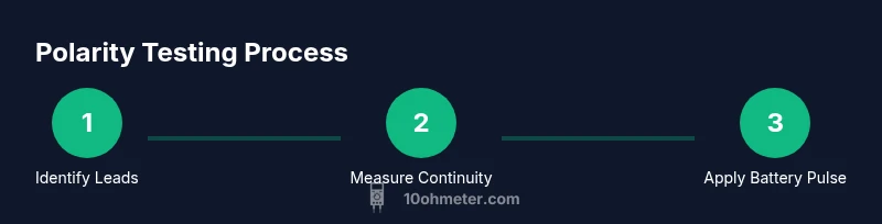
Prepare and identify leads
Power off the system and unplug the speaker. Visual inspect the two terminals and note any color coding or labeling. Attach alligator clips to each terminal to avoid direct wire contact and maintain a clean test setup.
Tip: Label the terminals (P for positive, N for negative) before you begin to prevent mix-ups later. - 2
Check coil continuity with the multimeter
Set the multimeter to the lowest resistance range and measure across the two speaker terminals. A stable, non-infinite resistance confirms coil continuity and no open circuit.
Tip: If you see a very high or infinite resistance, there may be a broken coil or disconnected lead. - 3
Attach a safe DC pulse
Connect a brief, low-voltage DC source (1.5 V) to the two terminals using the clips. Do not hold the connection; remove the battery immediately after observing any movement.
Tip: Keep pulse under a second to minimize risk of speaker damage. - 4
Observe cone movement to infer polarity
Watch the speaker cone when the battery is connected. The terminal that causes the cone to move outward when connected to the battery’s positive side is the positive terminal of the voice coil.
Tip: If there is no noticeable movement, double-check the connection and ensure the test is brief. - 5
Verify by reversing leads
Disconnect the pulse and swap the leads. Apply the pulse again and confirm that the cone moves opposite to the previous observation. This confirms which lead is positive and which is negative.
Tip: If the movement is the same, recheck the connections or consider a non-polarized test method. - 6
Label, document, and recheck
Mark the confirmed positive lead on the speaker and record the polarity for future wiring. Recheck coil continuity after the pulse to ensure the coil wasn’t damaged.
Tip: Document the test results with the speaker model and enclosure for future reference.
Your Questions Answered
Can a multimeter tell me speaker polarity directly?
No. A multimeter mainly checks continuity and resistance. Polarity is a function of the wiring and the system phase, which requires a battery test or audio signal test to confirm.
A multimeter alone can’t reveal polarity. You’ll need a test signal or a battery check to confirm which lead is positive.
Is it safe to connect a battery to the speaker for polarity testing?
When done briefly with a low-voltage source, the risk is minimal. Keep pulse times very short and monitor the cone for any overheating.
Yes, if you use a small battery for a fraction of a second and watch for any unusual heat or noise.
What if there are two voice coils in a woofer?
Polarity testing should be done on each coil separately if accessible. If not, refer to the manufacturer’s wiring diagram to avoid cross-wiring the crossover network.
Test each coil individually if possible; otherwise, follow the manufacturer’s diagram.
Can I use an AC test signal instead of a DC pulse?
An AC test signal helps verify phase alignment without DC exposure, especially when a speaker is connected to a complex network. Listen for phase differences between channels.
Yes—an AC test can confirm polarity with less risk of damage when used carefully.
What should I do if I hear no difference when swapping leads?
Double-check the wiring, ensure the speaker is the component under test, and consider an enclosure with a cross-over that might mask polarity. Try a simpler setup with just the driver.
If swapping leads doesn’t change the sound, recheck connections and test setup for hidden crossovers.
Why is documenting polarity important?
Documenting polarity saves time on future projects and prevents miswiring when replacing drivers or reassembling systems.
Keep a quick wiring note so you wire every future speaker the same way.
Watch Video
Key Takeaways
- Identify the positive lead with a safe DC pulse test.
- Use continuity to confirm coil integrity before polarity testing.
- Verify results by reversing leads and observing the audible/visual response.
- Document polarity for consistent future wiring.