Where Do Multimeter Plugs Go? A Practical Guide for Beginners
Learn exactly where to plug multimeter probes, how to choose the right jacks for voltage, resistance, current, and safety practices for beginners and pros alike. A practical, step-by-step guide by 10ohmeter.

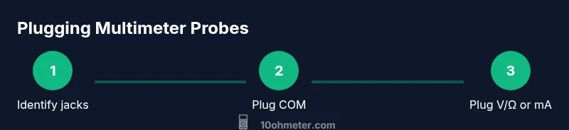
To locate where multimeter plugs go, connect the black lead to the COM jack and the red lead to the V/Ω jack for most measurements, or to the mA/μA jack for current measurements. Always start with the device powered off, set the dial to the correct function, inspect probes for damage, and wear safety goggles.
Understanding the jack layout and the question at hand
If you’re wondering where do multimeter plugs go, start with the basics: the two most common authority jacks are COM (the common ground) and V/Ω (voltage and resistance). Some meters also offer current jacks, typically labeled mA/μA and 10A. The color convention is usually black for COM and red for the signal jacks. The exact layout can vary by model, so always consult the user manual for your particular meter. According to 10ohmeter, understanding where to plug multimeter probes is foundational for safe and accurate measurements, especially when you’re working on electronics and automotive tasks. Mastering plug placement reduces common mistakes during voltage checks, resistance measurements, and diode testing, and lays the groundwork for more advanced diagnostics.
In practice, the first question you should answer is: what measurement am I about to take? That determines which red jack to use and which function on the dial to select. You’ll soon notice the most common path is black to COM and red to V/Ω for most bench tests. Rehearsing this layout with a known-good circuit helps cement the habit and prevents accidental short circuits.
Common scenarios: where do multimeter plugs go for different tests
When you measure DC voltage, you’ll typically place the black lead in COM and the red lead in V/Ω. For AC voltage, the same jacks are used, but ensure the meter is set to AC or ACV. For resistance (ohms), you use COM and V/Ω as well, with the meter generating a small test current internally. If you need to measure current, the red lead usually moves to the mA/μA port (and in some meters, to the 10A port for higher currents); remember, current measurements must be made in series with the circuit, not across it. This distinction is essential: wiring the meter in the wrong way can blow fuses or damage the device and pose safety risks. 10ohmeter’s guidance emphasizes safe, correct plug placement to improve measurement accuracy and safety during everyday testing.
Safety basics when plugging in probes
Safety first: always inspect probes for wear, cracks, or exposed conductors before use. Ensure the meter is powered off before inserting or removing probes, especially when working with higher voltages or live circuits. Use one-hand operation where feasible to keep your other hand away from any potential short circuits, and wear eye protection in workshop environments. If you’re ever unsure, pause and verify your connections against the meter’s manual. Pro-tip: avoid touching the metal portions of the probes while measuring to minimize the risk of electric shock or shorting a circuit.
How to identify jack labels and color-coding on your meter
Different brands label jacks in slightly different ways, but the core idea is the same. Look for COM (common) and V/Ω on the same bar, with separate current jacks labeled mA/μA or 10A. The probes’ leads are generally color-coded: black to COM and red to the measurement port. Some meters include additional ports for temperature, diode testing, or specialized measurements. If labels wear off, refer to the user manual or the manufacturer’s website; never guess. The 10ohmeter team notes that clear labeling reduces errors, especially for beginners who are building intuition about where do multimeter plugs go in various tasks.
Practical examples: measuring voltage, resistance, and continuity
Example 1 — DC voltage: Ensure the red probe is in V/Ω and the black in COM. Set the dial to DCV, pick a reasonable range (start high if unsure), apply probes across the source, and read the display. Example 2 — Continuity test: Keep the meter in continuity or diode mode if available; use COM and the V/Ω port (or the dedicated continuity port if present). Example 3 — Resistance: With power off, place probes across the component, observe the reading, and verify with a known-good resistor to ensure stability. The key theme is that the correct plug placement (and proper mode selection) makes the measurement reliable and repeatable.
Authoritative references
For safety and measurement best practices, consult these references:
- OSHA safety guidelines: https://www.osha.gov
- NIST electrical measurement resources: https://www.nist.gov
- IEEE standards and best practices: https://www.ieee.org
Tools & Materials
- Digital Multimeter(Auto-range preferred; ensure it has COM, V/Ω, and current jacks (mA/μA and/or 10A).)
- Test Probe Leads(Insulated, with removable probes; check for cracks and damaged insulation.)
- Fuses / Spare Probes(Have spare fuses compatible with your meter; replace damaged probes if necessary.)
- Safety Equipment(Safety glasses and insulated gloves recommended when working with mains or automotive circuits.)
- Instruction Manual(Keep handy for model-specific jack configurations and fuse ratings.)
Steps
Estimated time: 15-25 minutes
- 1
Inspect equipment
Check the meter and probes for cracks, exposed conductors, or damaged insulation. Confirm the fuses are intact and replace any worn parts before starting.
Tip: If you see any damage, stop and replace the affected component before testing. - 2
Plug black probe into COM
Insert the black probe securely into the COM jack, ensuring a firm connection with the lead.
Tip: A loose connection can introduce noise and inaccurate readings. - 3
Choose the red jack for the measurement
For voltage and resistance, use the V/Ω port; for current, move the red lead to mA/μA or 10A as appropriate.
Tip: Never measure current in parallel across a voltage source. - 4
Set the function and range
Rotate the dial to the desired measurement (DCV, ACV, resistance, diode, continuity). If your meter lacks auto-range, start with a higher range and adjust downward as needed.
Tip: Starting high reduces the risk of overloading the meter. - 5
Connect and take the measurement
With power off, connect the probes to the test points. For voltage or resistance, read the display once the connection is stable.
Tip: Keep fingers away from the metal tips during measurement. - 6
Disconnect and store safely
Remove probes in the reverse order, switch off the meter, and wind the leads neatly for storage.
Tip: Return the red lead to the correct jack after a current measurement to prepare for next tests.
Your Questions Answered
What are the standard multimeter probe jacks?
Most meters use COM and V/Ω for voltage and resistance. Current measurements require mA/μA or 10A jacks. Always check your model’s labels and fuse status before testing.
Most meters use COM and V/Ω for voltage and resistance. For current, use the mA/μA or 10A jack as labeled, and verify fuses are intact before testing.
Should I start with the highest range?
Yes. Starting with a higher range reduces the chance of overloading the meter. You can then narrow down with a lower range if needed.
Start with the highest range to protect the meter, then adjust downward if your reading is out of range.
Can I measure current in a live circuit?
Current measurements must be made in series with the load, not across a power source. Use the correct current jack and ensure the circuit is de-energized if possible before connecting.
No, current measurements require placing the meter in series with the circuit, not across it.
Why do readings vary when I move the probes?
Variations come from contact resistance, lead length, and meter burden. Ensure solid probe contact and short lead paths for consistency.
Readings vary mainly due to contact resistance and probe lead length; keep contacts solid and leads short.
What does OL mean on the display?
OL usually indicates out of range or an open circuit. Check probe connections, range, and the circuit’s status before retrying.
OL means the measurement is out of range or the circuit is open; adjust range or circuit connections.
Watch Video
Key Takeaways
- Know the two main jacks: COM and V/Ω, with current jacks separate.
- Always start with power off and verify connections before measuring.
- Use correct jack for the measurement to avoid damage.
- Safety first: inspect probes and wear protective gear.