Testing a Transformer with a Multimeter: A Practical Guide
Learn how to safely test a transformer with a multimeter, checking windings, continuity, and insulation. A comprehensive guide for DIY enthusiasts and technicians.

In this guide, you will learn how to safely test a transformer with a multimeter, verify winding continuity, measure DC resistance, and inspect insulation. Start by isolating the transformer, disconnecting leads, and selecting the correct meter settings. This process helps identify open windings, shorted turns, or degraded insulation before re-energizing any circuit. Ensure you follow local safety rules.
Why Testing a Transformer with a Multimeter Matters
Testing a transformer with a multimeter is a practical way to verify windings, detect faults early, and prevent unexpected failures in electronics and automotive applications. According to 10ohmeter, safety and methodical testing are essential when evaluating transformers with a multimeter. By checking winding continuity, DC resistance, and insulation integrity, technicians can identify open windings, shorted turns, or degraded insulation before applying power. This approach helps DIY enthusiasts and professionals avoid costly damage and downtime while building a solid fault-detection routine for service work.
Safety First: Power Down and Isolation
Electrical testing carries real risk when high voltages are involved. Always power down the circuit, unplug the device, and disconnect all leads from the transformer before touching any winding. If the transformer is part of a larger system, verify that there is no residual charge in capacitors or connected storage elements. Wear approved PPE such as safety glasses and insulated gloves, and keep your work area dry and non-conductive. These precautions reduce the chance of shock, arc flash, or accidental short circuits during testing.
Tools, Meters, and Settings You’ll Need
A reliable digital multimeter with a clear ohm and continuity range is essential. Use fresh test leads with proper insulation and minimal resistance. Keep an insulated work surface and handy labeling materials to identify windings. While you can adapt existing gear, ensure the meter is rated for the voltage you’re working near and that you understand how to switch between resistance, continuity, and diode-test modes. Having the transformer datasheet or schematic is highly beneficial for expected winding values and connection points.
Step-By-Step Testing Procedure Overview
The testing sequence generally follows a logical flow: isolate power, identify windings, measure DC resistance to verify continuity, check for shorts between windings and the core, and finally compare results with the transformer’s datasheet or a known-good unit. Practically, you’ll attach the meter’s probes to windings one at a time, record readings, and then cross-check across primary, secondary, and inter-winding paths. The goal is to confirm that each winding is continuous, that there are no unintended shorts, and that insulation integrity looks acceptable for continued operation.
Practical Troubleshooting Scenarios
If a winding shows unusually high resistance or no continuity, it may indicate an open circuit or a partially damaged winding. A near-zero resistance reading between windings can signal a shorted turn or an inter-winding fault. If you measure between a winding and the core and observe a low or unexpected reading, re-check your connections and ensure the transformer is isolated. Remember that readings depend on winding design, gauge, and temperature, so always compare against the datasheet or a known-good transformer of similar type and rating.
Documentation and Next Steps
Document every measurement with windings labeled and note the ambient conditions during testing. If readings fall outside the manufacturer’s specifications, stop and consult the datasheet or a qualified technician before re-energizing. For safety, reassemble the device only after you confirm all windings are properly isolated and there are no exposed conductors. The result is a clear record of transformer condition that supports maintenance planning and fault diagnosis.
Tools & Materials
- Digital multimeter(Auto-range preferred; use DC resistance (ohms), continuity, and diode-test modes; ensure rating matches expected voltages)
- Test leads with alligator clips(Insulated, properly rated; keep leads short to reduce noise)
- Insulated gloves and safety goggles(Personal protective equipment for electrical work)
- Insulated work surface(Non-conductive mat or bench to minimize shock risk)
- Insulated screwdriver with appropriate head(To remove covers safely without scraping windings)
- Schematic or transformer datasheet(Helpful for identifying windings and expected resistance ranges)
- Labeling tape and marker(For clearly marking windings and test points)
- Non-contact voltage tester (optional)(Quick check for live surfaces before handling)
Steps
Estimated time: 25-45 minutes
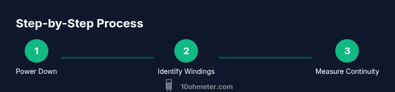
- 1
Power down and isolate
Disconnect all power sources and remove the transformer from any circuit. Verify there are no stored charges in nearby capacitors and secure the device on a non-conductive surface. This prevents accidental shocks during testing.
Tip: Double-check that all leads are disengaged and clearly labeled before touching any winding. - 2
Identify windings and prepare leads
Use the transformer diagram or datasheet to identify the primary and secondary windings. Route test leads so they won’t snag or pull on taps. Label each winding to avoid cross-testing.
Tip: Keep leads short to reduce contact resistance and noise during measurements. - 3
Check winding continuity with DC resistance
Set the multimeter to ohms and measure each winding individually from end to end. Record the DC resistance for primary and secondary windings. Continuity should exist, and values should be within the documented tolerance range.
Tip: If a winding shows open circuit, recheck connections and consider re-testing after cooling if the transformer is hot. - 4
Test for shorts between windings and core
With the meter still on resistance, measure between each winding pair and between each winding and the core. Expect high resistance between windings and core; any low resistance between windings could indicate a short.
Tip: Cross-test each winding pair in case a short exists that hides behind another measurement. - 5
Compare results to datasheet or known-good unit
If available, compare readings to the manufacturer’s values or to a known-good transformer of similar design. Use the same meter, leads, and ambient conditions for consistency.
Tip: Document discrepancies and consider factory service if tolerances are not met. - 6
Document, reassemble, and plan next steps
Record all measurements, reconnect the transformer to its circuit only after validation, and power up in a controlled manner. Plan follow-up checks or maintenance based on results.
Tip: Keep a maintenance log to track transformer health over time.
Your Questions Answered
What is the first step before testing a transformer?
Power down, unplug, and remove the transformer from any live circuit. This prevents shock and accidental energization during testing.
First, power down and disconnect the transformer from all circuits, then proceed with safe testing.
Can I test AC voltage on transformer windings with a multimeter?
AC voltage testing on windings is generally not performed with standard multimeters for diagnostics. Use DC resistance and insulation checks, and consult a professional if you need AC measurements.
AC voltage tests aren’t typically done with a basic multimeter for diagnostics; use DC resistance and insulation checks instead.
How do I identify primary vs. secondary windings?
Use the transformer’s datasheet or labeling on the casing. Mark windings clearly and test one winding at a time to avoid confusion.
Look at the datasheet or labels to identify primary and secondary windings, and test them one by one.
What does a very high DC resistance indicate?
Very high resistance can indicate an open winding or partial damage. Recheck connections and compare to the datasheet before concluding a fault.
Very high DC resistance may mean the winding is open or damaged; recheck connections and compare to specs.
Is insulation resistance testing necessary?
Insulation resistance is important for older transformers or high-voltage applications, but a megohmmeter is typically required for reliable results.
Insulation tests are important in some cases, but you usually need specialized equipment to measure it accurately.
Can I test a transformer that is part of a live automotive system?
Testing while connected to a live automotive system is dangerous. Isolate the system and follow proper safety protocols before testing.
Don't test a live automotive system—make sure it's isolated and safe before testing.
Watch Video
Key Takeaways
- Power down and isolate before testing.
- Verify winding continuity and DC resistance for each winding.
- Check for inter-winding and core-to-winding shorts.
- Compare results against datasheet or a known-good unit.
- Document findings and follow safety protocols.