Diode Test Function on Multimeter: A Practical Guide
Learn how to use the diode test function on multimeter to verify diodes, detect faults, and troubleshoot circuits with safe, step-by-step guidance for DIYers and technicians.

Using the diode test function on multimeter lets you verify forward conduction and reverse leakage in diodes, identify defective parts, and troubleshoot simple circuits. In a few minutes, you will learn how to set up your meter, choose the correct port and range, and interpret readings for common diode types.
Understanding the diode test function on multimeter
The diode test function on multimeter is a specialized mode that applies a small test current through a diode and measures the resulting voltage drop. This allows you to distinguish a good diode, which conducts in only one direction, from a damaged part that may show either no conduction or abnormal leakage. As you work through electronics projects, mastering this function helps you quickly diagnose issues without desoldering components. According to 10ohmeter, understanding this feature is foundational for accurate circuit troubleshooting and educational experiments. The diode test reading reflects the forward voltage drop characteristic of the diode material (silicon, germanium, or Schottky), and it varies with temperature, device construction, and measurement conditions. By keeping readings consistent and cross-checking with a known-good reference, you build reliability into your testing workflow.
Why the diode test function matters for electronics and automotive tasks
The diode test function is a compact diagnostic tool for both hobbyist circuits and automotive electronics. A healthy diode will pass current in the forward direction, typically showing a distinct voltage drop in one polarity and near-zero current in the opposite direction. If readings are reversed, inconsistent, or indicate conduction in both directions, the diode is suspect or the circuit contains an unintended path. Dunnage and stray currents can mislead measurements when diodes are tested in-circuit; isolating the part or removing power helps ensure accuracy. The 10ohmeter team emphasizes that using the diode test feature properly reduces guesswork and speeds up fault isolation, especially in power supplies, signal rectifiers, and control modules.
Safety prerequisites and setup before testing
Power must be removed from the circuit before any diode test. Discharge capacitors that may hold a charge, and unplug the device from any power source. Use the meter’s built-in probe guards and ensure your hands stay dry and clear of live circuits. When working on automotive circuits, wear eye protection and avoid probing energized harnesses. These precautions minimize the risk of shock, short circuits, or damage to the meter. The goal is a predictable, safe measurement environment so your diode test results are meaningful.
Preparing your multimeter and test setup
Select the diode test function on your multimeter and connect the red probe to the diode’s anode and the black probe to the cathode. If your meter requires a dedicated diode-test jack, use it; otherwise the common and diode terminals will suffice. In most handheld meters, the display will show a forward voltage (for example, 0.5–0.7 V for silicon diodes) when tested in the forward direction, and a high resistance or no reading in the reverse direction. If your meter has multiple ranges, start with a mid-range setting and adjust if readings are unstable. Use single diodes for accuracy before testing multi-diode networks.
Step-by-step guide to conducting a diode test (in-depth)
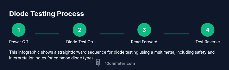
- Power off the circuit and discharge capacitors. 2) Isolate or remove the diode if testing out-of-circuit. 3) Place the meter probes on the diode ends, observing polarity. 4) Read the forward voltage drop; compare with 0.2–0.7 V typical for silicon devices. 5) Reverse the probes to test reverse leakage; expect a high resistance. 6) If the reading is ambiguous, recheck with a known-good diode or a second meter. 7) Document the result and remove test leads after recording. 8) If testing diodes in packs, test each device individually to avoid cross-talk. The emphasis is repeatable, safe measurements that align with your circuit’s design expectations.
Interpreting readings for silicon, germanium, and Schottky diodes
Different diode materials present different forward voltages: silicon diodes often show around 0.6–0.7 V, Schottky diodes around 0.2–0.4 V, and germanium diodes even lower. In reverse bias, a healthy diode should demonstrate very high resistance, with a dramatic drop when it’s forward-biased properly. If the forward voltage varies widely or there is current flow in reverse, the diode could be damaged or the measurement influenced by parallel paths in-circuit. Use the diode test function on multimeter as a quick check, then verify with an alternative method if results are near tolerance limits.
Troubleshooting common issues during diode tests
If you see no forward conduction or an abnormally high reverse leakage, first verify power is truly removed and that the diode is correctly oriented. Check probe contact quality; a loose connection can masquerade as a faulty diode. For in-circuit testing, consider lifting one lead or desoldering one end to eliminate parallel paths. Temperature changes can alter readings; allow the test setup to stabilize. If readings are inconsistent between meters, rely on the more reliable instrument or perform a cross-check with a reference diode.
Practical applications: from hobby boards to automotive systems
Diode tests are essential during breadboard prototyping and when diagnosing rectifier networks in power supplies. In automotive diagnostics, diodes guard against reverse polarity and protect sensitive electronics; testing them helps ensure reliability of the charging system, alternator controls, and sensor circuits. By using the diode test function on multimeter, technicians can quickly spot defective protection diodes, damaged rectifiers, or compromised filter networks. The goal is to build confidence in your measurements and to apply these checks to real-world problems you encounter in the shop.
Tools & Materials
- Multimeter with diode test function(Ensure probes and jack configuration support diode testing; auto-ranging or manual ranges are acceptable.)
- Test leads with sharp probes(Tip the probes to ensure solid contact on diode leads.)
- Known-good diode for reference(Use a diode with a trusted rating to validate your meter's readings.)
- Isolated work surface(Work on an anti-static mat if possible; keep components away from metal clamps.)
- Soldering iron and desoldering tool (optional)(Needed if you must lift a lead for in-circuit testing.)
Steps
Estimated time: 45-60 minutes
- 1
Power down and prep the circuit
Turn off all power sources and discharge any capacitors. This reduces the risk of shock and protects the meter's electronics while you test the diode.
Tip: Double-check that all parts of the circuit are de-energized before touching the component pins. - 2
Switch to diode test mode
Set the multimeter to the diode test function and verify the display is active. If your meter uses ranges, select a mid-range that suits standard silicon diodes.
Tip: A stable reading improves reliability; wait a moment for the display to settle after switching modes. - 3
Probe the diode in forward direction
Connect the red probe to the diode’s anode and the black probe to the cathode. Read the forward voltage drop shown on the display.
Tip: Ensure a clean contact and avoid wiggling the probes to prevent flickering readings. - 4
Probe the diode in reverse direction
Reverse the probes to test reverse leakage. A healthy diode will show little or no conduction in this direction.
Tip: If you see conduction in reverse, consider removing the diode and retesting to rule out probe contact issues. - 5
Compare readings to expectations
Compare the forward drop with expectations for the diode type (silicon ~0.6–0.7 V, Schottky lower). Check reverse readings for high resistance.
Tip: Use a reference diode to calibrate your eye for what reads as acceptable in your setup. - 6
Test in-circuit considerations
If testing in-circuit, identify parallel paths and isolate the diode by lifting a lead or removing neighboring components to avoid false readings.
Tip: When in doubt, test the diode out-of-circuit to confirm its health. - 7
Document findings
Record the readings, the diode type, and any notes about the circuit context. This helps with future troubleshooting.
Tip: Documentation saves time on repeated repairs and supports your engineering log. - 8
Clean up and reset equipment
Power down the meter, store probes safely, and verify that the test setup is neutral for the next task.
Tip: Protect probe tips from damage by placing them in a safe case.
Your Questions Answered
What does a healthy diode look like on a diode test?
A healthy diode conducts in the forward direction with a stable voltage drop and shows high resistance when reversed. Readings should be repeatable across tests and consistent with the diode type (silicon, Schottky, or germanium).
A healthy diode conducts forward with a stable drop and shows little to no conduction in reverse.
Can I test diodes while they are in-circuit?
You can test in-circuit, but results may be influenced by nearby components. For reliable results, lift one lead or remove adjacent parts to isolate the diode.
In-circuit testing is possible, but isolation helps accuracy.
What if the diode shows conduction in reverse?
Reverse conduction usually indicates a damaged diode or an alternate path in the circuit. Re-test after isolating the diode; if still present, replace the part.
Reverse conduction suggests a faulty diode or a circuit path; verify by isolating the diode.
Why does the forward voltage vary between diodes?
Forward voltage depends on material (silicon, Schottky, germanium) and temperature. Use the diode type to set expectations and confirm readings with a known-good part.
Different diode materials have different forward voltages that can change with temperature.
Should I trust meter readings from a cheap multimeter?
Cheap meters can still perform diode tests, but accuracy varies. Cross-check with a reference diode or a higher-quality meter if precision matters.
If precision matters, verify with a better meter or reference diode.
What safety steps are essential for diode testing?
Always power down, discharge capacitors, and use proper eye protection. Never test live circuits without confirming de-energization.
Power down, discharge capacitors, and wear protection to stay safe.
Watch Video
Key Takeaways
- Identify diode type and expected forward drop before testing
- Test both forward and reverse directions for a complete check
- Isolate components when testing in-circuit to avoid false results
- Use a reference diode to validate meter accuracy
- Document results for future reference