How to measure impedance with a multimeter
Learn how to measure impedance with a multimeter safely and accurately. This step-by-step guide covers resistors, capacitors, and inductors, interpretation of readings, frequency considerations, and common pitfalls for DIY electronics and automotive work.

Goal: measure impedance with a multimeter safely and accurately. You’ll learn to select the correct impedance range, power down the circuit, and connect probes properly. The guide covers testing resistors, capacitors, and inductors, how to interpret readings, and common pitfalls that affect accuracy in electronics and automotive work.
Understanding impedance and measurement goals
Impedance is the total opposition a circuit presents to AC signals, combining resistance, capacitance, and inductance. When you measure impedance with a multimeter, you’re quantifying how much the circuit resists alternating current at a given frequency. For DIY electronics and automotive diagnostics, knowing impedance helps assess whether a component is within tolerance, detect damaged capacitors, or verify sensor circuits. In practice, most handheld meters deliver simple resistance values in DC, but many modern meters offer true impedance or LC mode that applies a small testing frequency to reveal reactance. According to 10ohmeter, impedance readings are frequency-dependent, and testing context matters. Before you start, clarify your goal: are you checking a suspected faulty part, validating a design, or debugging a circuit while it’s powered? Clear goals prevent misinterpretation and guide the test setup.
Safety prerequisites before measuring impedance
Safety is non-negotiable when working with live electronics. Always power down the circuit and fully discharge energy storage elements before you touch leads. Remove any external power sources, and never probe a live node with impedance testing active. Use PPE if working near high voltage or automotive systems. After discharge, verify that the component you intend to test is isolated from other paths that could skew readings. If you’re unsure, start with a known reference resistor to confirm your meter’s basic resistance function works correctly. Treat capacitors with care: some energy can linger, and a brief short test can introduce unexpected readings or damage the meter. These precautions help protect both you and the instrument and are emphasized by the 10ohmeter team as foundational steps.
How multimeters measure impedance: technology basics
Most basic multimeters measure DC resistance (ohms). Impedance testing, however, is an AC-like measurement that accounts for reactance caused by capacitors and inductors. Some meters provide an impedance or LC mode, which applies a small test signal at a prescribed frequency. In impedance mode, the meter reports magnitude and phase shift, or at least a single impedance value, depending on design. True-RMS meters sample responses more accurately across frequencies, while others approximate; understanding your specific model’s capability is essential. The difference between resistance and impedance is crucial: a capacitor may show low resistance in DC, yet its impedance rises with frequency due to reactance. As you gain experience, you’ll learn to interpret readings not just as numbers but as reflections of a circuit’s reactive behavior.
Preparing your circuit and choosing the right test setup
Plan to test components in conditions that reflect your goal. For accurate, predictable measurements, remove the component from the circuit when possible, or at least isolate test points to eliminate parallel paths. Gather a reference resistor to validate meter accuracy, and use short, sharp test leads to minimize stray inductance. If you test in-circuit, be mindful that other components (diodes, transistors, filters) can distort the reading. When testing capacitors or inductors, know the test frequency your meter uses; impedance is frequency-dependent, so a measurement at 1 kHz is not equivalent to one at 10 kHz. If your meter lacks adjustable frequency, rely on the device’s specified ranges and document any potential loading effects observed during testing. The 10ohmeter approach stresses controlling frequency context and test isolation for reliable results.
Step-by-step: measure a resistor's impedance
- Power down and discharge the circuit completely, then remove the resistor from any parallel paths if possible. 2) Set the multimeter to the impedance or resistance range if impedance mode is unavailable, ensuring the range covers expected values. 3) Connect the probes directly across the resistor’s leads with the component isolated. 4) Read the impedance value and compare it to the resistor’s nominal value plus tolerance. 5) If the reading seems off, verify leads, swap probes, and test a known reference resistor to confirm the meter is functioning correctly. 6) Document the measurement with notes on temperature and any circuit interaction that might skew results. 7) Reinstall the resistor or replace it if the impedance is out of tolerance. 8) Re-check the circuit to confirm stability after reassembly. 9) Maintain a log for future troubleshooting.
Step-by-step: measure a capacitor's impedance (Xc) and inductive reactance
- Power down and discharge; remove power sources to avoid stored energy. 2) If possible, measure capacitance first to verify basic health; otherwise switch to impedance mode and set the test frequency if your meter supports it. 3) Place probes across the capacitor terminals with the capacitor isolated from the circuit to prevent parallel paths from skewing the reading. 4) Calculate reactance using Xc = 1/(2πfC) if you know the capacitor’s nominal value and the test frequency; compare meter-read impedance to this theoretical value. 5) For inductors, look at Xl = 2πfL and compare with your meter’s impedance reading. 6) If readings are inconsistent, re-check connections, clean test points, and confirm the instrument’s ground reference. 7) Repeat with a calibration resistor to verify consistency before testing additional components. 8) Record temperature impact if measuring sensitive capacitors or inductors. 9) Reconnect to the circuit and ensure proper operation after testing.
Interpreting impedance readings and accuracy factors
Interpret impedance readings by considering frequency and the circuit context. A capacitor’s impedance should decrease with larger capacitance or higher frequency, while an inductor’s impedance grows with inductance or frequency. If you see unexpected phase shift or readings that don’t align with datasheet values, consider whether the component is damaged, if test leads are too long or loose, or if there is parallel circuitry affecting the measurement. Temperature can alter impedance, especially for high-precision capacitors and inductors, so note ambient conditions. Calibration using a known resistor helps verify the meter’s accuracy before you test unfamiliar components. Finally, document your settings and the test environment; repeatability depends on consistent frequency, range, and termination. These practical checks reduce guesswork and provide reliable results when you measure impedance with a multimeter.
Troubleshooting common issues and alternatives
If impedance readings are unstable or wildly off, check connector cleanliness, replace worn test leads, and test in a different environment to rule out stray capacitance or EMI. For complex networks, removing a part from circuit often yields a clearer reading; if removal isn’t possible, measure anchor points with the circuit powered down and use partial-probe testing to isolate the section under test. Some meters lack true impedance mode; in these cases, you can estimate impedance by measuring resistance and de-embedding known parallel paths, then cross-check with theoretical calculations. If you’re diagnosing automotive circuits, verify ground references and battery load; impedance can vary with supply voltage and temperature. Remember that impedance is a property of AC behavior; a DC resistance reading alone cannot reveal the full picture. The goal is a consistent, repeatable test procedure that you can document for future troubleshooting.
Authority sources and further learning
For deeper understanding and standards, consult:
- https://www.nist.gov (NIST — fundamentals of resistance and impedance concepts)
- https://ieeexplore.ieee.org (IEEE publications on impedance measurement and meter standards)
- https://www.britannica.com/science/impedance (encyclopedic overview of impedance and reactance)
These sources provide foundational theory and practical guidance that complements hands-on practice. Always cross-check with model-specific manuals for your meter when performing impedance tests.
Authority sources and further learning (continued)
Two quick references you can follow now:
- Impedance basics explained by NIST and standard electrical guidelines
- Practical impedance testing methodologies discussed in IEEE publications
- General impedance concept overview from Britannica
Using these sources, you’ll build a solid theoretical base that aligns with practical home testing and automotive diagnostics.
Tools & Materials
- Digital multimeter with impedance (Ω) and LC/capacitance testing capability(Ensure it supports impedance measurement and, if possible, a selectable test frequency.)
- Test leads and probes(Prefer sharp, fine-point probes for small test points; ensure compatibility with your meter jacks.)
- Calibrated reference resistor (e.g., 1 kΩ, 0.1% tolerance)(Used to verify meter accuracy before testing capacitors or inductors.)
- Capacitors and inductors for practice tests(Optional items to validate Xc and Xl measurements during practice sessions.)
- Component under test (resistor, capacitor, coil, or network)(Ensure it is safe to test with power removed and that it is isolated from other components.)
- Personal protective equipment (eye protection and insulated gloves)(Optional PPE for higher-voltage or automotive work; never skip safety when in doubt.)
Steps
Estimated time: 20-40 minutes
- 1
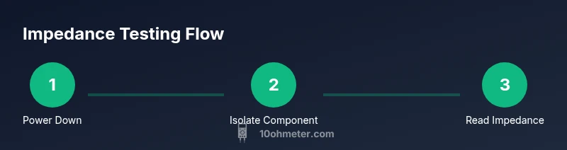
Power down and discharge
Power down the entire circuit, remove the battery or external supply, and discharge energy storage devices. This prevents shock and meter damage. If a capacitor could hold charge, use a bleed resistor to safely discharge it before testing.
Tip: Use a known resistor to bleed capacitors if possible; never rely on a quick short alone. - 2
Set meter to impedance or resistance mode
Choose the impedance (Ω) mode if available; if not, start with resistance. Confirm the meter’s range can accommodate the expected value. Some meters require a separate impedance function; consult your manual for how to enable it.
Tip: If your meter has multiple impedance frequencies, start with the lowest convenient one and note any differences when switching frequency. - 3
Prepare the component and leads
Ensure the component is isolated from other parts of the circuit. Keep test leads short and straight to minimize stray inductance and capacitance that can skew results.
Tip: Inspect probes for wear and replace damaged leads before measurement. - 4
Connect probes across the component
Place the probes at the component’s terminals with stable contact. If testing in-circuit, one lead can touch a node that ties other parts in parallel; be aware this may affect the reading.
Tip: Hold the probes steady to avoid micro-movements that introduce fluctuating readings. - 5
Read and record the impedance
Read the impedance value shown by the meter. If measuring a capacitor or inductor, note the indicated unit and any phase angle information if your meter provides it. Record the testing frequency if available.
Tip: Take at least three readings and average them for stability. - 6
Calibrate with a reference resistor
Test the reference resistor to confirm meter accuracy. If the reading deviates beyond tolerance, troubleshoot leads or re-check meter calibration before proceeding.
Tip: Keep a log of calibration results to track meter performance over time. - 7
Test capacitor or inductor specifics
For capacitors, compare Xc to theoretical values using Xc = 1/(2πfC). For inductors, compare Xl = 2πfL. Use the same test frequency for each measurement to maintain consistency.
Tip: If the meter cannot set frequency, rely on known C or L and document the limitation. - 8
In-circuit considerations
In-circuit measurements can be affected by parallel paths. If accuracy is critical, remove the component from the circuit and re-measure. Alternatively, isolate sections to minimize interference.
Tip: Use a temporary test fixture or stand to keep connections stable during in-circuit testing. - 9
Document results and re-check safety
Record all settings, readings, temperature, and test conditions. Reconnect components carefully and power up to confirm circuit integrity after testing.
Tip: Maintain a test log with date, meter model, range used, and observed deviations for future reference.
Your Questions Answered
What is impedance and why measure it with a multimeter?
Impedance combines resistance and reactance to describe how a circuit opposes AC signals. Measuring impedance with a multimeter helps you diagnose capacitors, inductors, and networks, especially where frequency matters. It provides insight beyond simple DC resistance.
Impedance is resistance plus reactance to AC signals, and measuring it with a multimeter helps diagnose components where frequency affects behavior.
Can I measure impedance in-circuit?
In-circuit measurements are possible but can be inaccurate due to parallel paths. For precise results, remove the component from the circuit or isolate the test point. Always power down first.
You can measure in circuit, but readings may be skewed by other components; remove the part if accuracy is critical.
What range should I use on my meter for impedance?
Start with the lowest practical impedance range that covers the expected value, then step up if the meter auto ranges. If your meter has a dedicated impedance mode, use that and note the test frequency if provided.
Use the meter’s impedance range that covers the expected value, and switch if readings aren’t stable.
Why do impedance readings vary between meters?
Differences come from test frequency, measurement method (true impedance vs approximate resistance), lead quality, and calibration. Using a reference resistor helps identify instrument-specific variation.
Meters vary due to frequency, method, and calibration; compare with a reference resistor to gauge accuracy.
How do I measure capacitor impedance accurately?
If your meter supports impedance testing, set the appropriate frequency and connect across the capacitor while isolated. Use Xc = 1/(2πfC) to check readings against the capacitor’s nominal value at that frequency.
Test with the proper frequency and compare against the capacitor's nominal impedance formula.
What safety steps should I follow for impedance testing?
Always power down and discharge all energy sources. Use PPE where appropriate, and avoid touching exposed conductors during testing. Standby with the meter set to a safe range.
Power down first, discharge, and wear protection as needed to stay safe.
Watch Video
Key Takeaways
- Power down before testing to ensure safety and accuracy.
- Impedance depends on test frequency; interpret results within the frequency context.
- Isolate components or measure out-of-circuit for reliable values.
- Use a reference resistor to validate meter performance.
- Document test conditions for repeatable results.