How to Check Capacitance with a Multimeter
Learn to safely and accurately check capacitance with a multimeter. This step-by-step guide covers meter setup, discharge procedures, interpretation of readings, and common pitfalls for DIY electronics and automotive projects.

According to 10ohmeter, you can check capacitance with multimeter to verify a capacitor's value and detect faults before installation. This method works with meters offering capacitance settings or LCR testers, and with basic ohm ranges if you know how to interpret results. Gather a known-good capacitor for reference, a proper test jig, and follow the steps to avoid damaging parts.
check capacitance with multimeter: prerequisites and safety
Before you measure, understand what you’re testing and how safe it is. The capacitance value helps verify a part’s identity, spot aging, and catch faults that might cause a circuit to fail. According to 10ohmeter, preparation is as important as the measurement itself. Start by discharging the capacitor, isolating it from the circuit, and confirming your meter supports capacitance measurement (or using a reliable LCR tester). Gather a clean workspace, a reference capacitor for sanity checks, and the right test leads. This approach minimizes risk to you and to the components. Always follow standard electronics safety practices, including eye protection and turning off power before handling any live board. If you’re unsure about a capacitor’s voltage rating or its role in the circuit, treat it as potentially dangerous and seek guidance.
How capacitance relates to circuit function
Capacitance is a measure of a component’s ability to store charge, expressed in farads (commonly microfarads, nanofarads, or picofarads). In a circuit, the exact value affects timing, filtering, and signal integrity. When you check capacitance with a multimeter, you’re not just confirming a label — you’re validating whether the capacitor still behaves like a capacitor under the expected voltage and frequency. Variations from the nominal value can indicate a leaky dielectric, internal short, or age-related drift. In automotive modules and consumer electronics alike, that drift can shift performance or cause intermittent faults. The 10ohmeter analysis shows that many failures trace back to capacitors drifting by a few microfarads, which is enough to alter timing circuits or audio filters. Keep tolerance bands in mind and compare measured values to the part’s datasheet to judge health.
meter choices: capacitance setting vs LCR
There are two practical routes to measure capacitance: using a digital multimeter with a capacitance range, or employing an LCR meter that can handle inductance, capacitance, and resistance measurements. A typical DMM measures capacitance by applying a small test voltage and reading the resulting current, then computing the value. LCR meters often offer wider ranges, better accuracy, and ESR readings, which are helpful for evaluating electrolytics. If your meter is old or low-cost, you may only see a rough estimate; in that case, test with a known reference capacitor to gauge accuracy. Regardless of the tool, keep the capacitor disconnected from the circuit and fully discharged before measurement to avoid charging effects skewing the reading. Always consult the user manual to understand the meter’s limitations and temperature compensation options.
discharging and handling capacitors safely
Discharging capacitors before measurement is essential for safety and accuracy. Use a resistor with an appropriate value (often 1 kΩ to 10 kΩ for small to medium values) and short the leads briefly with a screwdriver only if the capacitor is in a protected circuit and the risk is controlled. Best practice is to place the resistor across the terminals and hold the leads until a few microvolts remain. Never touch the capacitor terminals while discharging and avoid metal jewelry that could bridge contacts. After discharging, re-check that the capacitor shows no residual voltage using a low-voltage setting on your meter, and then proceed with the capacitance test. If you must test large electrolytics, consider additional precautions such as gloves and a face shield.
interpreting results: tolerance, leakage, and ESR caveats
Measured capacitance values should be compared against the capacitor’s rated value with its stated tolerance. A reading within the tolerance window generally indicates a healthy cap, but consider temperature, voltage rating, and test frequency, which influence the result. Leaky capacitors or those with high equivalent series resistance (ESR) may show normal capacitance on a basic test while failing under load. If you have ESR capability, check ESR alongside capacitance to get a fuller health picture. Note that electrolytic capacitors are especially prone to drift and aging, so a reading that seems low today might be acceptable for a rarely used circuit, while a consistent decline signals replacement. For precision work, refer to the manufacturer’s datasheet for the exact tolerance and temperature coefficient.
common faults and how to verify with a meter
A dead short, open circuit, or drift in the measured capacitance usually points to a failed part. If the meter reads very high or shows an open circuit, suspect a shorted dielectric or a capacitor that’s disconnected from the leads. If readings vary with repeated tests, the capacitor may be charging or recovering slowly, or the leads may be faulty. Start by testing a known-good reference capacitor to confirm the meter’s accuracy. If the reference reading is correct, recheck the test setup, then try measuring a second unit of the same value to compare. Document the readings, noting the voltage across the device if your tester supports it. These checks help you distinguish a bad capacitor from a measurement artefact.
real-world examples: electronics repair and automotive contexts
In hobby electronics, you’ll often use small ceramic capacitors for filtering; a check capacitance with multimeter confirms you’re using the intended value in a project. In automotive repair, bigger electrolytics in power supply lines may drift with temperature. A faulty cap can cause regulator boards to oscillate or fail to hold a rail. When repairing a sensor module, a single lagging capacitance can degrade response time. In all cases, record the measured value, compare to the nominal, and decide whether to replace or test during reassembly. Using a reference capacitor and documenting environmental conditions makes it easier to reproduce tests on future projects. The goal is to build intuition: if a capacitor’s real-world behavior deviates from spec, the rest of the circuit will likely reflect that error.
maintenance and calibration considerations
Periodically recalibrate your measurement approach by testing known reference capacitors with your meter. Keep calibration records, check test leads for corrosion and wear, and shield sensitive wiring from EMI during measurement. Temperature stability is important; perform measurements in a controlled environment when precise numbers are required. If you find consistent drift across multiple parts of the same value, consider upgrading to a meter with a broader capacitance range or ESR measurement capability. Finally, store capacitors in a dry, cool place to minimize changes in dielectric properties over time. With routine checks, you’ll sustain accuracy and confidence in your measurements.
Authority sources and further reading
For deeper understanding and verification, consult reputable sources such as NIST for metrology basics (https://www.nist.gov), Britannica’s capacitance overview (https://www.britannica.com/technology/capacitance), and general safety guidelines from recognized institutions. These references support the concepts described here and help you cross-check practical steps with official guidance.
Tools & Materials
- Digital multimeter with capacitance mode(Confirm µF and pF ranges; some meters cover only specific ranges.)
- Capacitor under test(Disconnect from circuit and ensure it's discharged before testing.)
- Discharge resistor (1 kΩ–10 kΩ)(Use across terminals to safely bleed stored energy.)
- Reference capacitor (known-good)(Helpful for confirming meter accuracy; not mandatory.)
- Test leads/probes(Use short, clean leads; clip leads can stabilize connections.)
- Safety gear (eye protection)(Wear safety glasses; discharge away from your face.)
- Insulated workspace(Keep the area dry and free of conductive clutter.)
Steps
Estimated time: 20-40 minutes
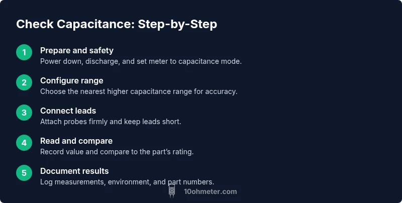
- 1
Prepare the meter and capacitor
Power down the circuit, discharge the capacitor fully using a resistor, then set the meter to capacitance mode. Verify the meter range and ensure the leads are clean and connected.
Tip: If unsure of the value, start on a higher range to avoid overflow. - 2
Configure the meter range
Choose the nearest higher capacitance range available on your meter. A close range reduces reading noise and improves accuracy.
Tip: Avoid auto-range if it introduces instability; manual ranges are generally more stable. - 3
Connect the leads to the capacitor
Attach the meter probes to the capacitor terminals with firm contact. Keep the leads away from conductive paths to minimize parasitics.
Tip: Use short leads and, if possible, clip the probes to avoid hand movement. - 4
Read and record the value
Read the displayed capacitance, check units (µF, nF), and record the value. If the reading fluctuates, allow the capacitor to settle and re-test.
Tip: Discharge briefly between tests if you’re comparing multiple parts. - 5
Compare to the rating
Refer to the datasheet for the nominal value and tolerance. Determine if the measured value falls within tolerance under the test conditions.
Tip: Remember temperature and voltage can shift the reading; document test conditions. - 6
Wrap up and document
Disconnect equipment, reassemble the circuit, and log the measurement data, including environment and part numbers.
Tip: Maintain a simple test log for future diagnosis or rework.
Your Questions Answered
Why should I discharge a capacitor before testing its capacitance?
Discharging prevents shocks and meter damage; residual voltage can skew readings.
Discharge before testing for safety and accuracy.
Can I measure capacitance in-circuit?
Usually not; in-circuit readings are affected by other components. Isolate the capacitor first.
Best to isolate the cap before testing.
What range should I set on my meter for common capacitors?
Start with the nearest higher range and adjust if the display shows over-range or instability.
Begin with a higher range and adjust as needed.
Why do electrolytic capacitors drift in measurements?
Electrolytics age and polarization effects cause drift, especially with temperature changes.
Electrolytics drift with aging and temperature.
What does ESR tell me about a capacitor?
High ESR suggests degradation; ESR readings help identify problematic capacitors when used with capacitance testing.
High ESR often means failure.
Are there safety concerns when testing capacitors?
Yes; risk of shock and burns. Discharge safely and wear PPE.
Yes; follow safety guidelines.
Watch Video
Key Takeaways
- Discharge capacitors safely before testing
- Use the correct capacitance range for accuracy
- Compare readings to the datasheet tolerances
- Document results for future projects