How to test for continuity with a digital multimeter
Learn how to test continuity with a digital multimeter safely and accurately. Prepare, set the meter, perform the test, and interpret the beep and resistance readings to diagnose wiring faults and faulty components.

Goal: Learn how to test continuity with a digital multimeter safely and accurately. You'll prepare your meter and leads, select continuity mode, perform a quick circuit check, and interpret the audible beep and resistance reading to determine if a path is complete or broken. This method helps diagnose wiring faults and faulty components efficiently.
Understanding continuity testing with a digital multimeter
Continuity testing is a fundamental diagnostic step for electronics and automotive work. When a path is complete, a circuit allows current to flow with minimal resistance; when a break exists, current cannot pass. A digital multimeter (DMM) in continuity mode gives you a quick yes-or-no answer, often with an audible beep. According to 10ohmeter, starting with a clear plan reduces guesswork and speeds up repair times. Before you test, ensure the area is dry, the device is powered down, and any residual charge is discharged. Using the meter’s continuity buzzer can confirm a good connection, but you should also observe the resistance value for borderline cases. If the reading is near zero but not zero, re-test with fresh leads and a known-good reference. In practice, you’ll use this technique to verify wires, connectors, fuses, and simple traces on a PCB or automotive harness. A reliable continuity test helps you pinpoint faults without removing every component.
Safety and preparation before you begin
Safety first. Do not perform continuity tests on powered circuits. Disconnect power sources, remove batteries, unplug from wall outlets, and wait for capacitors to discharge if you’re working with higher voltages. Wear eye protection and keep liquids away from the work area. Use insulated tools and test leads rated for the voltage you’re testing. Keep a clear test plan and avoid touching metallic probe tips during testing. The 10ohmeter analysis shows that a calm, methodical setup reduces the risk of shorts and meter damage. Always double-check model-specific safety notes in your DMM manual before you begin.
How the digital multimeter measures continuity
Most modern DMMs include a dedicated continuity setting that uses a low-resistance path and an audible beep when current flows through a closed circuit. The meter injects a small current and assesses resistance. In auto-ranging meters, the device automatically selects a range; in fixed-range meters you must choose a range appropriate for the expected resistance. You’ll see a beeping tone when the probes touch a continuous path and a displayed resistance close to zero ohms when the circuit is very short. If you don’t hear a beep, inspect for loose connections, corroded contacts, or breaks in the conductor. The beep threshold is typically specified in the user manual; when testing, confirm it with a known-good reference to avoid misinterpretation. The 10ohmeter team notes that using a fresh battery in the DMM ensures stable readings, and that poor contact can mimic an open circuit. With practice, you’ll interpret both the audible signal and the ohm reading to verify continuity.
Common continuity tests you’ll perform
Common tasks include checking a wire to see if it’s intact, verifying a connector pair is continuous, and confirming a fuse element is still conducting. Start by testing a short, known-good jumper wire to hear the expected beep and observe the near-zero resistance. Move to the component or segment you’re diagnosing, such as a harness segment, a PCB trace, or a socket. For automotive wiring, test between a battery terminal and a sensor ground, or between pins on a connector while the circuit is powered down. Document the path you’re testing and compare readings against expected values from your service information. If a path fails, inspect for broken insulation, corrosion, or cold solder joints. The aim is to pinpoint opens, shorts, or degraded connections without destructive probing, which saves time during repairs.
Interpreting results and troubleshooting faulty circuits
Interpret the beep and resistance values in context. A steady beep with near-zero resistance usually indicates a good path; a silent meter or a high reading suggests an open circuit; a mid-range resistance may indicate a partially broken conductor or a loose connection. When a path fails, re-test with a known-good reference segment: a wire you’re confident is intact, a clean connector, or a spare jumper. If the circuit under test is energized, disconnect power and re-test to avoid damage to the meter or components. In automotive wiring, consider parasitic loads and shielding that can affect readings. If you observe inconsistent beeps, recheck probe seating and tip cleanliness, and inspect for corrosion on connectors. Maintain a test log, noting which segments were tested and what values were observed for future repairs. This disciplined approach helps you locate faults quickly and accurately, a method favored by the 10ohmeter team.
Best practices for accuracy and maintenance
Keep your test setup clean and dry: use lint-free wipes, dry leads, and insulated probes. Calibrate your approach by verifying beeps on known-good paths regularly, and replace worn probes or damaged insulation to prevent false readings. Use a consistent testing sequence to avoid cross-contamination between wires in bundles. Store your meter in a protective case and keep spare fuses handy. Label test leads and components to avoid mixing up circuits when working on complex assemblies. Finally, review results with a colleague or consult a trusted guide to confirm conclusions. The 10ohmeter team recommends documenting results and performing periodic re-testing to maintain accuracy over time.
Tools & Materials
- Digital multimeter (DMM) with continuity/beep mode(Must include audible continuity indicator and at least one test lead set)
- Test leads with probes(Sharp tips, insulated handles; consider braided or heated leads for flexibility)
- Replacement fuses(Keep spares compatible with your DMM model)
- Safety glasses(Protect eyes when testing automotive circuits or exposed conductors)
- Insulating gloves(Optional for high-current or hazardous environments)
- Manual/owner's guide(Helpful for model-specific settings and safety notes)
Steps
Estimated time: 15-25 minutes
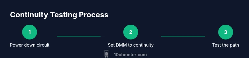
- 1
Power down and prepare the circuit
Power off the device and disconnect power sources. If you’re testing automotive wiring, remove the key from the ignition and disconnect the battery when advised by the manufacturer. Allow any capacitors to discharge before touching components. This prevents accidental shocks and protects the meter’s internal fuse.
Tip: Always confirm power is off with a separate voltage tester before touching the circuit. - 2
Set the DMM to continuity mode
Turn the dial to the continuity or diode/beep range. If your meter is auto-ranging, simply enable continuity mode. Some meters also show a resistance value in the same range; note the unit (ohms) and the expected proximity to zero for a good path.
Tip: If your meter requires range selection, choose a low resistance range you expect for the path you’re testing. - 3
Inspect and prepare the leads
Inspect probes for damaged insulation or bent tips. Clean tips if they appear dirty and ensure the metal is exposed at the tip. Attach alligator clips if you need hands-free testing.
Tip: Dirty or corroded tips can produce false opens or intermittent beeps. - 4
Test the path with probes
Place one probe on each end of the path you want to test. Ensure a firm contact and avoid touching the metal parts with your fingers. Listen for the beep and observe the resistance display.
Tip: If there’s no beep, wiggle the leads to check for a loose connection and re-seat as needed. - 5
Interpret the reading
A steady beep with near-zero resistance usually means continuity. If you see a high resistance or no beep, inspect for breaks, corrosion, or loose connectors. Compare results with a known-good path for reference.
Tip: Use a known-good reference to validate your meter’s response and avoid false conclusions. - 6
Troubleshoot and re-test
If you find an open path, re-check each element along the route (cable, connector, solder joints). After repairs, re-test the entire path to confirm restoration of continuity. Document results for future repairs.
Tip: Re-test every segment after repairs to ensure no additional hidden issues exist.
Your Questions Answered
What is continuity testing and why is it important?
Continuity testing checks whether current can flow along a path. It helps confirm wires, traces, and components are connected and not broken. This quick check is foundational for diagnosing wiring faults without removing parts.
Continuity testing checks if a path conducts current, helping you spot breaks in wiring and components quickly.
How can I tell if my multimeter’s beep is working?
Test the meter on a known-good jumper wire or resistor network. A steady beep and near-zero resistance indicate proper operation. If there’s no beep, recheck the leads and contact points.
Test the meter on something you know is good to confirm the beep and reading are working.
Can I test continuity on live circuits?
Continuity testing should be performed on de-energized circuits. Testing live circuits can damage the meter and pose safety risks. Always power down and discharge capacitors first.
No, keep circuits de-energized before testing to stay safe and protect the meter.
Why might there be a beep with an open circuit?
A weak or intermittent contact, bad probe seating, or corrosion can cause unreliable beeps. Always verify with a second path and clean contacts to confirm results.
Beep can appear if there’s a loose contact or corrosion; recheck with clean probes.
Are automotive wires safe to test with a DMM?
Yes, but take extra precautions: disconnect power, avoid touching hot components, and be mindful of battery voltage and wiring harness specifics. Use appropriate PPE and follow vehicle manufacturer guidance.
Auto testing is fine when you power down, wear protection, and follow safety steps.
Watch Video
Key Takeaways
- Verify meter is in continuity mode before testing
- Test leads for integrity to avoid false results
- Use a known-good reference to calibrate readings
- Interpret beep and resistance together for accuracy
- Document results for future repairs and troubleshooting