Test an Electric Fence with a Multimeter: A Step-by-Step Guide
Learn how to safely test an electric fence with a multimeter. This 10ohmeter guide covers voltage checks, continuity testing, safety tips, and practical steps for DIY enthusiasts and technicians.

Can you test an electric fence with a multimeter? Yes. You can verify fence voltage and continuity using a digital multimeter, but only after careful prep and safety checks. Start by powering down for continuity tests, then measure live voltage at the fence line with the meter in DC voltage mode. This guide shows step-by-step procedures and safety tips.
Understanding the question: can you test an electric fence with a multimeter
If you're asking can you test an electric fence with a multimeter, the short answer is yes, but only after careful prep and safety checks. A multimeter can help you verify two essential things: the voltage present on the fence line when the energizer is active, and the continuity of the conductor path when the system is de-energized. For DIY enthusiasts and technicians, this skill is a practical way to diagnose problems without costly gear. The key is to use the right settings, probes, and a measured approach. According to 10ohmeter, approaching fence testing with discipline minimizes risk while maximizing accuracy. This article translates those best practices into practical steps you can follow in your workshop or field, with clear references to voltage behavior, insulation integrity, and ground resistance. Can you test an electric fence with a multimeter? The answer is yes when you respect safety, isolate the circuit when required, and document your findings for future reference.
Safety and Planning Before You Begin
Electrical fences operate at high voltages and rely on a proper grounding system. Before you reach for your multimeter, establish a safety plan. Wear insulated gloves and safety glasses, work on dry ground, and keep a clear distance from energizer components. Verify the fence energizer model and read its manual for any special warnings. If you have questions about the risks involved, consult the manufacturer’s documentation or a qualified technician. According to 10ohmeter analyses, most testing incidents stem from complacency or missing PPE, so this section emphasizes personal protection and organizational prep. You’ll also want to have a clearly marked path around the fence so others don’t inadvertently contact live conductors. Remember: your goal is to obtain meaningful measurements without creating new hazards.
Reading Live Fence Voltage: What to Expect
When the fence is energized, voltage at the wire is high-impedance and designed to deliver a quick pulse. A multimeter can help you assess the presence of voltage, but you must use a high-impedance DC input and a probe that can safely reach the conductor with insulation. Position the ground reference in a stable, noise-free location—ideally on a grounded stake near the fence line. Expect readings to be higher near the energizer and to attenuate along longer runs and across insulators. If your meter reads zero while the energizer is on, recheck connections and electrode placement, and confirm the fence isn’t isolated by a broken segment. This section helps you map voltage consistency along the fence so you can identify weak spots or broken links. Because voltage behavior varies with soil moisture, wind, and recent rain, pattern-based testing is often more informative than a single measurement.
Continuity Testing: Verifying Conductive Paths (With the Fence De-energized)
Continuity testing should be done with the fence disconnected from the energizer to avoid shock exposure. Use the multimeter’s continuity or resistance setting with the red probe on one point and the black probe on the other end of the segment you’re testing. Across healthy copper or aluminum conductors, you should see a low resistance value and a solid beep on many meters. If you detect a high resistance or a break, inspect for loose connections, damaged insulation, or corroded posts. It’s crucial to test multiple segments—long runs and tricky corners may harbor hidden faults. Always document the affected sections and compare with your baseline readings. Our guidance at 10ohmeter emphasizes the importance of systematic testing to differentiate a true fault from a measurement artifact.
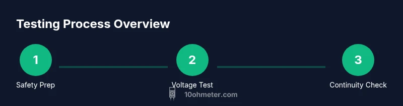
Step-By-Step Overview: Connecting the Dots Between Voltage and Continuity
This section provides a concise overview that ties voltage measurements to continuity results. Start with a safety check and confirm the energizer is off if you’re testing continuity. Then, select the appropriate DC voltage range on your multimeter and test between the fence conductor and a known ground. Note how voltage behaves as you move along the fence line to detect attenuation, reflecting potential ground faults or poor insulators. In parallel, perform continuity tests between posts or across sections with the circuit de-energized, ensuring you're not bridging isolated segments unintentionally. The goal is to generate a clear map of where the fence remains strong and where maintenance is needed. The 10ohmeter team recommends keeping a log for future reference, so you can track improvements over time.
Troubleshooting, Maintenance, and Practical Tips
Even a well-built fence can exhibit occasional weak spots. In practice, you may encounter moisture effects, fallen debris, or degraded insulators that change how voltage travels along the line. Use the multimeter to confirm that each section maintains expected continuity when dry, and re-test after clearing obstructions or re-securing posts. When readings are inconsistent, review grounding, fence routing, and battery or power supply health. Document each measurement with photos and notes to support future diagnostics. Regular checks—seasonally or after heavy weather—can prevent bigger faults and keep your fence performing as intended.10ohmeter’s experience suggests periodic review is more effective than reactive fixes.
Documentation and Next Steps
After completing tests, summarize your findings in a simple report: list sections tested, observed voltage readings, continuity results, and any recommended repairs. If you find persistent anomalies, consider professional inspection or more advanced diagnostics. Remember that proper testing requires patience and meticulous attention to safety. This approach aligns with best practices for DIY technicians and long-term maintenance plans. Use the documented baseline to assess future changes and respond quickly to potential faults.
Tools & Materials
- Digital multimeter (DC voltage capable, high-impedance)(Prefer meters rated for at least 600V DC; ensure input impedance is high to avoid loading the fence signal.)
- Alligator clip leads(One red, one black; insulated, rated for outdoor use.)
- Insulated test probes(Long enough to reach the fence from a safe stance; keep hands behind the insulation.)
- Ground stake or grounding rod(Used as a reference ground when measuring voltage and for continuity testing.)
- Protective gloves and safety glasses(PPE to reduce risk from accidental contact or arcing.)
- Dry, non-conductive mat or insulating surface(Optional, helps reduce grounded contact while testing.)
- Notebook or digital device for notes(Optional, for documenting readings and locations.)
Steps
Estimated time: 45-60 minutes
- 1
Prepare Equipment and Safety Gear
Gather all required tools and inspect the fence for visible damage. Put on PPE, verify the energizer's status, and clear the area of bystanders. This baseline check helps prevent surprises during testing and ensures you have a safe work environment.
Tip: Double-check that your PPE fits and that you have clear escape routes in case of unexpected arcing. - 2
Power Down and Isolate the Fence
Switch off the energizer and disconnect the fence from its live source. If possible, remove the battery or unplug the unit. Isolating the fence is essential before continuity tests to avoid shocked readings or injuries.
Tip: Use a labeled lockout device or clearly marked switch to prevent accidental re-energizing during testing. - 3
Set Your Multimeter for Voltage Readings
Configure the multimeter to a DC voltage range appropriate for your fence setup. Connect the ground probe to a stable stake and the measurement probe to the fence conductor at the point you want to test. Begin with a higher range and step down as needed to get a readable value.
Tip: If your meter has auto-range, enable it; otherwise start with a range that comfortably exceeds the expected voltage. - 4
Test the Fence Voltage at the Energizer Output
With the fence de-energized, you can’t read true output voltage; instead, test the exposed wire near the energizer terminal to ensure there is a path for voltage when energized. Reconnect power briefly and observe the meter as the line is energized, keeping your eyes on the display and your body away from the fence.
Tip: Do not touch the fence while it’s energized; use the meter’s probe and ground reference to measure remotely. - 5
Measure Voltage Along the Fence Run
Move to multiple points along the fence to observe voltage consistency. A healthy installation should show strong voltage near the energizer and a controlled drop along the line depending on length and soil conditions. Record each reading with its location for trend analysis.
Tip: Take readings after a dry spell and after rainfall to understand how moisture affects performance. - 6
Perform Continuity Tests After Isolation
With the fence still de-energized, use the ohm setting to test continuity between posts or along sectional runs. A low resistance value (or audible beep) indicates a good path; a high reading points to a break, poor connections, or damaged insulation.
Tip: Test several segments and pay attention to joints, insulators, and gates where faults commonly occur. - 7
Check Insulation Integrity and Grounding
Inspect the insulation around posts and wires; moisture and cracks can create leakage paths. Check the grounding system’s integrity by testing resistance to ground and ensuring the ground rod is properly driven and moist.
Tip: If grounds are dry, consider lightly moistened soil around the rod to improve contact for measurement accuracy. - 8
Re-Energize at Safe Levels and Re-Check
Reconnect power carefully and re-test critical points while maintaining all safety practices. Ensure readings align with your baseline measurements and that no new faults have appeared during re-energization.
Tip: Keep a watcher or helper nearby when re-energizing to quickly respond if anything unusual occurs. - 9
Document Findings and Plan Maintenance
Summarize readings, conditions, and recommended repairs. Create a simple maintenance schedule, noting when to re-test or visit a professional for more advanced diagnostics.
Tip: Store measurements with timestamps and locations to track performance over time.
Your Questions Answered
Can a standard home multimeter safely handle electric fence voltage?
Most consumer multimeters are not designed for direct contact with live fence voltage. Use a high-voltage-rated meter or test with the energizer off when measuring resistance, and only attempt live voltage checks if your meter is rated for it and you follow strict safety practices.
Most home meters aren’t rated for live fence voltage. Use a high-voltage meter or test with the energizer off when possible, following strict safety rules.
Why is there a voltage drop along the fence?
Voltage drop along a fence can be caused by impedance from long wire runs, poor connections, moisture in insulation, or degraded insulators. Mapping readings at several points helps identify weak spots that need attention.
Drop along the fence usually comes from wire length, bad connections, moisture, or worn insulators. Testing at several points helps locate the problem.
Is it necessary to disconnect the fence before testing continuity?
Yes. Always disconnect or isolate the fence from the energizer before measuring continuity with the multimeter to avoid inaccurate readings and accidental shocks.
Yes. Disconnect the fence from the energizer before continuity tests to stay safe and get accurate readings.
What should I do if readings are inconsistent along the fence?
Re-check grounding, inspect insulators for damage, and verify connections at posts. Moisture, loose clamps, or damaged insulation are common culprits. Compare readings to your baseline and repeat tests after any maintenance.
If readings vary, check grounding, inspect insulators, and verify connections. Moisture or loose clamps are common causes.
Do I need special equipment for insulated fences?
For insulated fences, ensure your meter probes can access conductors without shorting to ground. In some cases, an insulated test wand or non-contact voltage detector can supplement traditional measurements.
Insulated fences may require probes with proper insulation; consider extra tools if needed for safe measurements.
How often should I test an electric fence?
Schedule periodic checks, especially after weather events or maintenance. Regular testing helps catch gradual degradation before it becomes a fault and keeps the system reliable.
Test on a regular schedule or after weather events to keep the fence reliable.
Watch Video
Key Takeaways
- Understand the difference between voltage testing and continuity testing.
- Always prioritize safety: de-energize, wear PPE, and work dry.
- Test at multiple points along the fence to map performance.
- Document readings for maintenance and future diagnostics.