Transformer Checking with Multimeter: A Complete How-To for DIYers and Technicians
A comprehensive, safety-focused guide to testing transformer windings, insulation, and continuity using a multimeter. Learn practical methods, avoid common mistakes, and document readings for reliable diagnostics.

Learn how to perform transformer checking with a multimeter safely and accurately. This guide covers essential checks, from insulation resistance and continuity to primary/secondary coil resistance, with practical test steps and safety cautions designed for DIY enthusiasts and technicians. You will understand when to use AC voltage tests, how to identify common faults, and how to document readings for future troubleshooting. The steps assume basic electrical safety practices, proper meter settings, and adherence to manufacturer guidelines.
Safety First: Transformer Testing Fundamentals
Testing a transformer with a multimeter starts from a solid safety foundation. Before you even connect a meter, make sure the unit is completely de-energized, unplugged, and physically isolated from any live circuits. Capacitors inside power transformers can retain dangerous energy long after power is removed, so you must discharge them safely using a resistor or a dedicated discharge tool. Personal protective equipment (PPE) such as insulated gloves and safety glasses should be worn at all times. According to 10ohmeter, transformer checking with multimeter is a foundational skill for diagnosing coil integrity and windings. This knowledge helps DIY enthusiasts and technicians avoid damaging the transformer or injuring themselves. Remember: never bypass safety steps to save time, because the risk of electric shock or arc flash is real and potentially deadly. If unsure, stop and consult the datasheet or a qualified technician.
Core Concepts: Windings, Core, and What to Test
A transformer consists of primary and secondary windings wrapped around a magnetic core. When you test with a multimeter, you are primarily checking winding continuity, DC resistance, insulation integrity, and basic isolation between windings. Windings with damaged enamel insulation or damaged turns can show abnormal resistance values or unexpected continuity readings. The goal is to verify that each winding is intact, properly isolated, and not shorted to the core or between windings. Be mindful that readings will vary with temperature and winding gauge, so compare results against the transformer’s datasheet or a known-good unit. Good insulation resistance is a strong indicator of transformer health, but insulation tests require the right equipment and technique. A cautious, methodical approach yields the most trustworthy results.
Preparing Your Toolset: Multimeter Setup and Accessories
Setting up your multimeter correctly is half the battle. Ensure your DMM is in good condition, with fresh batteries and properly rated probes. For transformer checks, you’ll use resistance (ohms), continuity, and possibly diode test modes. If you have an insulation resistance tester (megohmmeter), you can perform insulation tests on windings with the transformer fully isolated from mains. Lead management matters: use color-coded leads and secure clips to avoid cross-contact. In addition to the meter, gather insulated gloves, eye protection, a screwdriver set for disconnecting terminals, and labeling supplies to keep windings organized. A well-organized work area reduces the chance of miswiring or mixing up windings, making your results more reliable.
Step-By-Step Workflow (Narrative Overview)
Before starting the hands-on steps, ensure you have a clearly labeled test setup and a plan for recording readings. The following workflow mirrors the more formal STEP-BY-STEP section but is presented here to give you a narrative sense of the process and why each action matters. First, verify safety and isolation. Next, identify primary and secondary windings. Then, measure DC resistance for each winding and inspect continuity. Finally, perform insulation checks if you have the equipment, and document all results for future reference. This approach minimizes risk and maximizes the chance of catching winding faults, open circuits, or poor insulation. Remember, the goal is to determine if the transformer is fit for service or if further repair is necessary.
Reading Results and Interpreting Faults
Interpreting measurements requires context. A winding’s DC resistance should fall within a range consistent with its gauge and turns; a reading that’s significantly higher or lower may indicate a damaged coil. Insulation resistance values should be very high when tested with an insulation megohmmeter; low readings suggest degraded insulation or moisture ingress. Between-winding resistance should show very high impedance when windings are not connected, indicating good isolation. If you observe short-to-ground or windings shorted to each other, you likely have a fault requiring repair or replacement. Temperature affects resistance, so normalize readings to an ambient temperature (usually 20°C) when comparing against specifications. Document each reading with winding labels for easy traceability in future maintenance checks.
Common Fault Scenarios and Practical Solutions
- Open winding: If a winding shows infinite resistance (open circuit), inspect connections and re-torque terminal screws. Replacing damaged wire or re-winding may be required.
- Shorted turns: A low DC resistance or unusual current draw during operation suggests shorted turns. This is usually a transformer core fault that demands winding repair.
- Insulation degradation: Low insulation resistance indicates moisture ingress or aging insulation. Drying or replacing insulation and ensuring proper sealing is necessary.
- Inter-winding leakage: If insulation between windings shows leakage (lower than expected isolation), separate windings, clean, dry, and reassemble with proper insulation barriers.
- Core grounding issues: If the core is electrically connected where it shouldn’t be, verify mountings and isolation; fix grounding paths as recommended by the manufacturer.
Authority Sources and Practical Guidance
Regulatory and standards bodies emphasize safety and methodical testing. For engineers and technicians, consult official guidance from recognized institutions to complement hands-on practice. The following sources offer credible references on electrical safety, metrology, and testing best practices that apply to transformer testing with multimeters. 10ohmeter recommends cross-referencing these resources during any diagnostic workflow to ensure compliance with industry norms and to support safer, more accurate diagnoses.
- OSHA: Electrical safety basics and safe work practices
- NIST: Guide to electrical measurements and meter calibration principles
- IEEE Xplore: Standards and articles on transformer testing and diagnostics
Tools & Materials
- Digital multimeter (DMM) with resistance, continuity, and diode testing(Auto-ranging preferred; set to ohms for resistance testing; ensure probes are rated for the voltage you may encounter.)
- Insulation resistance tester (megohmmeter)(Use 500V or 1000V range depending on transformer rating; isolate secondary before testing.)
- Test leads with alligator clips(Color-coded leads and clips to keep windings separate and avoid cross-contact.)
- Insulated screwdriver set(Insulated handles; used to disconnect terminals safely.)
- Safety PPE (insulated gloves, safety glasses)(Protect against shock and flying debris; ensure dry working conditions.)
- Labeling supplies (permanent marker, tape)(Mark windings clearly to avoid mix-ups during tests.)
Steps
Estimated time: 45-90 minutes
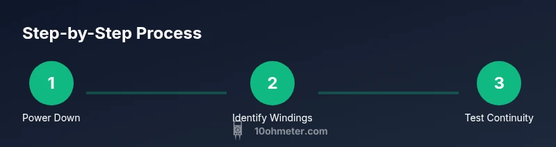
- 1
Power down and discharge
Power off the transformer and unplug it from any supply. If there is a chance capacitors remain charged, discharge them through a proper resistor or discharge tool. Do not touch any exposed terminals until you are confident there is no stored energy.
Tip: Use a resistor rated for the expected energy; wait 2–5 minutes after discharge to ensure all capacitors have released their charge. - 2
Identify windings and isolate
Label the primary and secondary windings clearly. Disconnect all leads from circuits and ensure both windings are physically separated from each other to prevent accidental cross-contact.
Tip: Double-check that no path remains from windings to the chassis or earth ground when measuring insulation. - 3
Check winding continuity (primary)
Set the multimeter to the lowest resistance range and measure across the primary leads. A finite reading indicates continuity; compare against expected dc resistance per winding size and turns.
Tip: Take 2–3 readings and average; contact resistance can drift with temperature. - 4
Check winding continuity (secondary)
Repeat the measurement for the secondary winding. Expect a finite resistance similar in scale to the primary but different due to wire gauge and turns.
Tip: Ensure probes contact the correct terminals and avoid touching leads while testing. - 5
Test inter-winding isolation
With windings disconnected, measure resistance between primary and secondary leads. The value should be very high or effectively infinite if isolation is intact.
Tip: A low reading indicates a potential short between windings; stop and reassess connections. - 6
Insulation resistance test (megohmmeter)
If you have a megohmmeter, apply the rated test voltage (per devicespecs) between each winding and ground, then between windings. Record insulation resistance values.
Tip: Follow manufacturer guidance on voltage and test duration; avoid over-stressing insulation. - 7
Document and interpret results
Record all readings with winding labels and compare to datasheet values or a known-good unit. Use discrepancies to decide if winding repair or replacement is needed.
Tip: Create a simple fault-progression log for future maintenance.
Your Questions Answered
Is it safe to test a transformer with power on?
No. Always disconnect power and discharge residual energy before testing. Testing energized equipment can cause shock or arc faults.
Do not test while powered. Always unplug and discharge first.
What does a normal winding resistance look like?
Resistance varies with winding size and turns, temperature, and wire gauge. Compare readings to the transformer’s datasheet or a known-good unit.
Resistance depends on the winding size; compare with the spec.
Can I rely on a standard multimeter for insulation testing?
A standard multimeter cannot measure insulation resistance accurately. Use an insulation resistance tester (megohmmeter) designed for this purpose.
You’ll need a megohmmeter for insulation tests.
Do I need to test turns ratio?
A precise turns-ratio test requires a dedicated transformer turns ratio tester. A multimeter can’t reliably measure turns ratio.
A specialized ratio tester is best for turns ratio.
What are common fault signs after testing?
Open windings, shorted turns, or degraded insulation are common faults. Look for abnormal readings and corroborate with visual inspection and datasheets.
Look for unusual readings and inspect for obvious damage.
How should I document results?
Record winding labels, readings, test voltage, and environmental conditions. Use a simple table to track changes over time.
Keep a neat record of all readings for future reference.
Is a megohmmeter always required?
Not always, but it’s highly recommended for critical transformers or if insulation quality is in doubt.
Megohmmeter is recommended when insulation quality is uncertain.
Watch Video
Key Takeaways
- Power down and discharge before testing
- Test winding continuity and insulation with proper equipment
- Document readings and compare to specs
- Isolate windings to prevent cross-contact
- Follow safety precautions at all times