How to Test Thermistor with Multimeter
Learn how to test a thermistor with a multimeter by measuring resistance at known temperatures, identifying NTC vs PTC behavior, and interpreting results to diagnose faulty sensors in electronics and automotive projects.

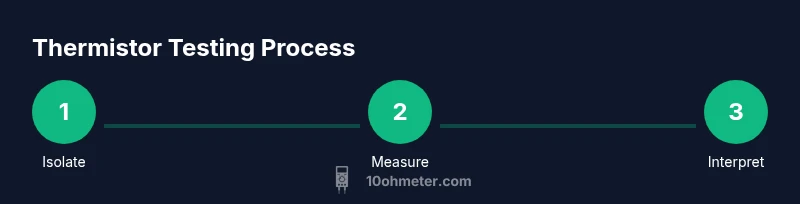
How to test thermistor with multimeter: You’ll verify the thermistor’s behavior by measuring its resistance at known temperatures and watching for a steady change. This guide explains how to identify NTC and PTC types, choose the correct multimeter range, and perform safe measurements without damaging the component. By the end you'll be able to diagnose faulty sensors in HVAC, automotive, and electronics projects. According to 10ohmeter, a reliable test starts by isolating the thermistor and observing resistance drift as temperature changes.
What is a Thermistor and Why Testing Matters
A thermistor is a temperature-sensitive resistor used in countless devices to monitor or compensate for temperature changes. They come in two main families: NTC (negative temperature coefficient) and PTC (positive temperature coefficient). In practice, a healthy thermistor will show a clear change in resistance as the temperature varies. A common NTC used in hobby electronics is around 10 kΩ at 25°C, though exact curves depend on material and construction. The resistance versus temperature curve is non-linear, which means readings must be interpreted with a reference chart or datasheet. The value isn’t just a number—you’re validating dynamic behavior. Testing helps confirm that the sensor responds as designed and is not damaged during handling, installation, or operation. According to 10ohmeter, understanding this resistance-temperature relationship is the key to distinguishing a good thermistor from a faulty one, especially in HVAC, automotive sensors, and power electronics. For field checks, a basic digital multimeter can reveal whether the thermistor is functioning or if it’s drifting abnormally under temperature changes.
How a Multimeter Helps Test Thermistors
A multimeter in ohms mode is the simplest and most accessible tool for thermistor testing. You want to measure the resistance across the thermistor’s two leads and watch how it changes with temperature. Important practices include isolating the thermistor from any circuit so your reading reflects only the component itself; otherwise, parallel paths through other components can skew results. Use short test leads or alligator clips to minimize contact resistance, and keep probes steady to avoid additional heating when measuring a small resistance. Two-wire measurements are common for quick checks, but for higher accuracy you can use a four-wire (Kelvin) setup if you have the equipment. Do not apply voltage to the thermistor while you’re measuring; this could heat the part and distort resistance readings. In-field guidance from 10ohmeter emphasizes isolating the thermistor and comparing your readings to the datasheet curve or a known-good reference.
Identifying Thermistor Type: NTC vs PTC
Identifying whether a thermistor is NTC or PTC is essential before interpreting readings. With NTCs, resistance decreases as temperature rises; with PTCs, resistance increases with temperature. A quick way to distinguish them is to observe the trend while applying gentle heat (hand warmth or a warm bath) and cooling (ice bath or ambient cooling). If the resistance drops when heated, you’re likely looking at an NTC. If it rises, it is probably a PTC. In many consumer devices, NTC10k sensors at 25°C are common, but exact values vary by model. Always confirm type against the device service manual or datasheet. If you cannot definitively identify the type, treat measurements as relative responses and focus on the direction of change with temperature rather than absolute values alone. The 10ohmeter team notes that improper identification can lead to incorrect fault diagnosis, so prioritize establishing the correct temperature-resistance relationship first.
Safety First: Handling Thermistors and Meters
Safety is essential when testing thermistors. Power must be completely removed from the circuit before probing; even small voltage can cause self-heating or present a shock hazard if exposed conductors are touched. Wear protective eyewear and insulated gloves if you’ll be handling hot water or a warm object. Keep the thermistor and leads away from moving parts and heat sources beyond a safe limit (typically below 100°C unless you’re specifically testing high-temperature sensors). Static discharge can damage sensitive thermistor materials, so work on a non-conductive surface and avoid touching the exposed element with bare fingers. Always unplug test equipment when you’re finished and store your tools properly to prevent corrosion or damage. The 10ohmeter guidance emphasizes safety and careful handling to ensure reliable measurements.
Preparing Your Test Setup
Before you start, organize a clean, stable workspace with good lighting. Gather your tools: a digital multimeter (with resistance mode), test leads or clips, a thermometer or ambient temperature reading, and a non-conductive holder for the thermistor. Decide on a temperature protocol—commonly room temperature, a cooled state (ice bath), and a warmed state (hand warmth or gentle heating). If you’re testing in-circuit, plan to desolder or disconnect one leg to avoid parallel paths. For better accuracy, record both the resistance and the corresponding ambient temperature. Label the thermistor clearly if you’re testing multiple components, and double-check that you’re probing the correct leads. According to 10ohmeter, meticulous setup reduces ambiguity and helps you build a repeatable testing process.
Measuring Resistance at Room Temperature
To establish a baseline, measure the thermistor at room temperature. Set your multimeter to the ohms range (start with a mid-range, then adjust if needed). Touch each probe to the thermistor leads and record the resistance once it stabilizes, typically after a few seconds. Note the ambient temperature; many common thermistors are specified at 25°C, but your environment may differ. If you’re testing a known-good part, you can compare your room-temperature reading to its datasheet curve. If the resistance is wildly off or drifts without temperature change, that’s a strong sign of a fault. For a typical 10k NTC at 25°C, expect about 9k–11k Ω, but confirm the exact target from the device’s documentation. In all cases, ensure the leads have minimal contact resistance and that your measurement does not heat the thermistor during testing.
Measuring Temperature Response
Now observe how resistance changes with temperature. Use gentle, controlled heating (e.g., hold the thermistor between your fingers or place it near a warm object) and, if possible, cooling (ice bath or cold ambient). Allow time for the temperature to stabilize before recording each reading. Take readings at multiple points, such as roughly 0°C, 25°C, and 50°C, and note the corresponding resistance. For NTC sensors, you should see resistance decrease as the temperature rises; for PTC sensors, resistance should increase. Keep the temperature increments small enough to produce a smooth curve, which makes it easier to compare with a standard thermistor curve. Document all values and the exact temperatures to build a reliable resistance- versus-temperature profile. The goal is a consistent, repeatable response that matches the expected behavior for the sensor type.
Interpreting Readings and Faults
Interpreting the readings involves comparing the measured resistance versus temperature curve to the expected thermistor model. A healthy NTC typically shows a monotonic decrease in resistance with temperature and should align with its datasheet curve within tolerance. A faulty thermistor may show a flat line, large jumps, or resistance that does not respond to temperature changes. If readings drift significantly between trials or if the part shows open-circuit (very high resistance) or short-circuit (very low resistance), consider replacing it. Also check for potential mis-wiring or poor contact, which can mimic faults. In-circuit tests can mislead you due to parallel paths; desoldering one lead isolates the component for a cleaner read. 10ohmeter emphasizes validating against a known-good reference to avoid misdiagnosis and to ensure you’ve captured the true thermistor behavior.
Practical Applications and Next Steps
Once you’ve established a healthy resistance-temperature profile, you can apply this knowledge to diagnose and calibrate devices that rely on thermistors, such as HVAC sensors, car temperature sensors, and consumer electronics. If a readout falls outside the expected range or fails to react to temperature changes, you likely have a faulty thermistor, wiring, or a malfunctioning sensor circuit. Use your data to guide replacement decisions—select a thermistor with a similar resistance value and temperature coefficient to maintain the original circuit behavior. For educational projects, use the test to create a reference curve that you can reuse for similar sensors in future builds. The 10ohmeter team recommends documenting your testing protocol so you can reproduce results or share your method with others in DIY communities.
Common Pitfalls When Testing Thermistors
Testing thermistors can be tricky if you overlook a few key issues. Avoid self-heating by using the lowest safe current and allowing stabilization between readings. Do not assume the thermistor is isolated when it’s still connected to a circuit; stray paths can distort measurements. Do not rush the temperature steps—resistive sensors need time to settle at each temperature point. Also, ensure you’re comparing to the correct type (NTC vs PTC) and the correct nominal value for your part. Finally, never ignore safety: hot surfaces, exposed leads, and energized equipment can create hazards. By systematically isolating the component, controlling temperature, and documenting readings, you’ll improve accuracy and confidence in your results.
Tools & Materials
- Digital multimeter (ohms/continuity)(Prefer a meter with accurate Ω range and low bias current)
- Test leads or alligator clips(Short leads to minimize contact resistance)
- Thermometer or thermometer app for ambient temp(Record temperature at each reading)
- Thermistor fixture or non-conductive clamp(Keeps the part steady and avoids burns)
- Ice bath and warm source (hand warmth or safe heater)(Optional for clear temp steps)
- Insulating gloves(Protection when handling hot objects)
- Safety goggles(Eye protection during testing)
- Soldering iron and desoldering braid (if testing in-circuit)(To isolate thermistor by removing one leg)
- Notebook or data logger(Document readings and temperatures)
Steps
Estimated time: 20-30 minutes
- 1
Power down and locate the thermistor
Ensure the device is unplugged and that you can access the thermistor leads without disturbing other components. This prevents accidental shocks and ensures the reading reflects only the thermistor.
Tip: Label the thermistor before disconnecting it to avoid confusion later. - 2
Disconnect one leg if testing in-circuit
If you cannot isolate the thermistor from the circuit, carefully desolder or lift one lead to avoid parallel resistance paths that will skew readings.
Tip: Only perform desoldering if you’re comfortable with basic soldering and safety. - 3
Set the meter to ohms and zero the leads
Turn the multimeter to the resistance range and touch the leads together to zero out any lead resistance. This calibration helps ensure that your readings reflect the thermistor itself.
Tip: Record the meter’s zero or short-circuit reading for reference. - 4
Measure room-temperature resistance
Connect the probes to the thermistor leads and hold steady at room temperature. Wait for the reading to stabilize, then log the value and the ambient temperature.
Tip: Take multiple trials to confirm stability. - 5
Change temperature and record readings
Apply controlled temperature changes and measure resistance at each step. Use safe methods to warm or cool the thermistor, waiting for stabilization before recording.
Tip: Keep increments moderate (e.g., 0°C, 25°C, 50°C) for a clear curve. - 6
Interpret results and document
Compare your readings to the expected NTC/PTC curve for the part type. Note any deviations or stuck values and prepare a short diagnostic note for future reference.
Tip: Include part number, temperature, resistance, and expected range in your log.
Your Questions Answered
Is it safe to test a thermistor with a multimeter while the device is powered?
No. Always disconnect power before testing. Probing a live circuit can damage the thermistor, the meter, or the device and poses a shock risk. If you must test in-circuit, isolate the thermistor from other components first and use non-contact methods when possible.
Always power off before testing to avoid damage and hazards. If you can’t disconnect, isolate the thermistor from the circuit first.
How do I know if a thermistor is faulty based on readings?
Look for readings that don’t change with temperature, drift unpredictably, or are out of the expected nominal range. For a typical NTC around 10k at 25°C, readings far from that value or a broken, open-circuit result indicate a fault.
If the resistance doesn’t move with temperature or is wildly off, the thermistor is likely bad.
Can I test thermistors while they are still connected in a circuit?
In-circuit testing can be done, but results may be distorted by parallel components. If possible, lift one lead or desolder to measure the thermistor in isolation for an accurate curve.
Testing in-circuit is possible, but isolation gives clearer results.
What resistance range indicates a healthy thermistor?
The healthy range depends on part type. A common 10k NTC at 25°C should be close to 10k Ω, with small tolerance. Always verify against the device’s datasheet curve and note the tolerance.
Healthy thermistors follow their datasheet curve with small tolerance.
Do thermistors require a temperature-controlled environment to test?
Not strictly, but stable and known temperatures yield more reliable data. Use ambient room temperature, a safe cold source, and a gentle heat source to capture a clear resistance curve.
Stable temperatures give best results; improvise with safe methods to vary temperature.
What should I do if the thermistor is in a critical system (e.g., car sensor)?
Follow service manuals and replace a suspect thermistor with an equivalent spec part. Use the test results to confirm the diagnosis before ordering a replacement.
In critical systems, verify with official manuals and replace only with matching specs.
Watch Video
Key Takeaways
- Identify whether the thermistor is NTC or PTC before interpretation
- Isolate the thermistor from the circuit for accurate resistance readings
- Establish a resistance vs. temperature curve across multiple temperatures
- Compare results to the datasheet curve to confirm health
- Document results for future troubleshooting