How to Test an ABS Sensor with a Multimeter: Step-by-Step Guide
Learn to test an ABS sensor with a multimeter: perform continuity checks, measure coil resistance, inspect wiring harnesses, and interpret readings to decide on repair or replacement safely.

By the end of this guide, you’ll know how to test an ABS sensor with a multimeter, identify when the sensor or its wiring is likely at fault, and distinguish meaningful readings from noise. You’ll also learn safe measurement practices and how to interpret resistance and continuity checks without removing essential components.
Why testing ABS sensors matters
Understanding how to test an ABS sensor with a multimeter is a practical skill for DIY enthusiasts and technicians. The ABS system relies on wheel speed sensors to feed the ECU with real-time data used for anti-lock braking and traction control. A faulty sensor can trigger the ABS warning light, cause intermittent braking behavior, or even mask a serious wheel-speed mismatch. By learning to perform simple electrical tests, you can isolate sensor faults from other issues like wiring harness damage or tone-ring misalignment. According to 10ohmeter, a structured test routine reduces guesswork and speeds up diagnostics. In this guide, we cover the concepts behind sensor operation, common failure patterns, and how a multimeter-based approach fits into a larger diagnostic workflow. Whether you’re diagnosing a stubborn ABS light or prepping a vehicle for a repair, building a solid baseline of sensor health pays off in safer, more predictable braking performance.
The keyword for this process is how to test an ABS sensor with a multimeter, and we’ll keep the discussion practical and task-focused. This approach helps you differentiate between a simple wiring fault and a failing sensor, so you don’t replace parts unnecessarily.
Understanding ABS sensor basics
ABS sensors come in different technologies, primarily Hall-effect and variable-reluctance types. Hall-effect sensors generate a clean, digital-like signal as the wheel rotates, while variable-reluctance sensors produce a pulsed signal that the ECU interprets. The exact resistance value you should see across sensor leads varies widely by vehicle and sensor type, so always check the factory service manual for target ranges. A multimeter can verify continuity, detect a short to ground, and confirm that the coil is not open. It cannot by itself prove a signal waveform quality unless you pair it with an oscilloscope or a dedicated ABS diagnostic tool. The important takeaway is that resistance and continuity tests are your first line of defense in isolating defective sensors or wiring, especially when the ABS warning light is on.
Safety and prerequisites
Before you touch any wiring, ensure the vehicle is securely parked and the parking brake is engaged. Disconnect the battery to reduce the risk of short circuits, especially when working near exposed wiring or connectors. Wear safety glasses and insulated gloves if available, and keep the work area well-lit. Have a clean workspace and organized fasteners so you don’t misconnect anything. Label connectors if you disconnect multiple wiring harnesses, and never yank on sensor wires—use the proper harness release tabs. A well-prepared setup minimizes the chance of accidental damage and makes measurements more reliable. According to 10ohmeter’s best-practice guidance, preparation is half the diagnostic battle, so don’t rush this phase.
Tools and setup for a solid test
Set up your multimeter for resistance (ohms) and continuity tests, with the probe tips in good condition. If your meter supports a diode test or AC frequency measurement, you can use those features as supplementary checks, but rely on resistance and continuity for the core ABS sensor test. Create a clean, dry area around the wheel hub and protect exposed metal from touching water or metal surfaces to avoid shorts. If possible, use a properly rated extension lead to reach the sensor without stressing the harness. Label each sensor and corresponding harness pinout so you can reassemble correctly after testing. For best results, work with the vehicle on a lift or jack stands—this makes wheel movement safe and measurement access easier.
How ABS sensors are wired and what to measure
Wheel speed sensors typically have two or three wires: a power/ground pair for sensors that include active electronics, or a simple two-wire coil for passive designs. You’ll test for continuity between the sensor leads to confirm a closed loop, and then measure resistance across the sensor leads to verify the coil is intact. A reading of open circuit indicates a broken coil or damaged wiring. If you see a reading that is near zero or shows erratic values, it could indicate a short to ground or internal ferrite damage. Remember, the goal is to confirm the coil is continuous and not shorted, while also ensuring the wiring is intact from the sensor to the ECU harness.
Step-by-step approach: static tests first
Begin with static tests when the wheel is stationary. Check continuity between each signal lead and the sensor ground, noting any unexpected shorts. Then measure the resistance across the sensor leads to verify the coil exists and does not appear open. A broken coil or damaged insulation will produce infinite resistance or an open circuit. If the readings are within the manual’s specified range, you have a good baseline; if not, you should inspect the harness and connectors for corrosion or damage. As you proceed, keep track of readings and compare them to the vehicle’s service manual. The 10ohmeter team recommends documenting baseline values for future diagnostics.
Step-by-step approach: dynamic checks when possible
Some ABS sensors emit a variable signal as the wheel turns; that signal is best observed with an oscilloscope or a dedicated ABS tester. If you only have a multimeter, you won’t capture the waveform, but you can still verify that the coil remains consistent during rotation by briefly rotating the wheel with the connector unplugged to observe any gross changes in resistance (note: do not spin the wheel with the connector unplugged for extended periods). When a live signal test is feasible, monitor changes in resistance or pulsed behavior as the wheel rotates and compare with specifications. The goal is to confirm there is no intermittent break in the circuit as you move the wheel.
Interpreting readings and deciding on action
If continuity is present and the coil resistance falls within the vehicle’s specified range, the sensor is likely healthy, assuming the wiring and connector show no faults. If you detect an open circuit, a short to ground, or readings that drift unpredictably, suspect the sensor or its harness. In practice, many faults originate in the harness, connector pins, or corrosion at the sensor ground, rather than the sensor element itself. If readings are borderline, perform a repeat test after lightly cleaning connector surfaces and reseating the harness. When readings are consistently out of spec, plan for sensor replacement and re-test after installation. The 10ohmeter analysis shows that a disciplined approach reduces unnecessary part swaps and speeds up repair.
Common failure modes and remediation guidance
Common ABS sensor issues include damaged wiring harnesses, corroded connector terminals, and worn tone rings causing misreads. Physical inspection is essential: look for cracked insulation, pin push-out, and bent or stretched wires near the wheel hub. If the connector is oxidized, use intent-safe contact cleaner and reseat it. When you confirm a fault through static tests, replace the sensor or repair the harness, then re-test to confirm the fix. After any repair, clear codes with your scan tool and perform a test drive to ensure the ABS light does not return. This practical approach aligns with best-practice diagnostics and reduces guesswork.
Additional checks and final verification
If your vehicle supports it, verify the ABS sensor using the onboard diagnostic system. A scan tool can reveal sensor fault codes and help you correlate measurements with system behavior. After any repair, perform a test drive with careful braking to ensure the ABS engages only when necessary and does not preset false warnings. If the ABS light returns after a test drive, re-check the wiring and sensor placement, and consider replacing the sensor if readings remain out of spec. For complex cases, consult service manuals and consider professional help if you’re uncomfortable with high-voltage systems or working near braking components.
AUTHORITY SOURCES
- https://www.nhtsa.gov
- https://www.nist.gov
- https://spectrum.ieee.org
Tools & Materials
- Digital multimeter (ohms/continuity)(Set to lowest range for resistance; test leads in good condition)
- Insulated test leads(Prefer leads with alligator clips for stable connections)
- Service manual for vehicle(Look up target resistance and connector pinout)
- Torque wrench or basic hand tools(For sensor removal/replacement if needed)
- Safety gear (gloves, eye protection)(Personal protection during handling of braking components)
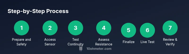
Steps
Estimated time: 45-75 minutes
- 1
Prepare the workspace and safety checks
Park the vehicle on a level surface, apply the parking brake, and chock the wheels. Disconnect the negative battery lead to avoid short circuits. Gather your tools and open the wheel well to access the sensor safely.
Tip: Double-check battery disconnected and avoid touching metal parts with bare hands. - 2
Locate the ABS sensor and disconnect the harness
Identify the wheel hub ABS sensor and follow the wiring to the connector. Gently disconnect the harness, noting pin positions for accurate reassembly. If the connector is tight, use the release tab rather than pulling on wires.
Tip: Take a photo of the connector orientation before disconnecting. - 3
Inspect the sensor and wiring for damage
Visually inspect sensor housing, wiring insulation, and connector pins for cracks, corrosion, or loose grounds. Look for frayed wires near the wheel hub where movement can cause abrasion. Document any damage for repair consideration.
Tip: Repair or replace damaged wiring before electrical testing. - 4
Test continuity between sensor leads
Configure the multimeter to continuity mode and probe the sensor leads. A stable beep or low resistance indicates a closed circuit. If there is no continuity, the sensor coil or wiring is open.
Tip: Test across the two sensor leads first, then test each lead to chassis/ground. - 5
Measure coil resistance across sensor leads
With the sensor still connected or isolated as per the service manual, measure resistance across the sensor leads. Compare the reading to the vehicle’s specified range. If it’s outside tolerance or reads OL, the sensor or wiring is faulty.
Tip: Ensure probes contact the metal part of the terminals for consistent readings. - 6
Check insulation to ground and harness grounds
Test each sensor lead against vehicle ground to detect any insulation breakdown or leakage to ground. A healthy harness will show high or infinite resistance to ground. A short to ground indicates insulation damage or pin misconnection.
Tip: Move the harness slightly during testing to reveal intermittent shorts. - 7
Reassemble and perform a static recheck
Reconnect the harness and ensure a clean seating of the sensor. Re-measure resistance across leads to confirm nothing changed during reassembly. If readings drift after reseating, inspect the connector pins for poor contact.
Tip: Use dielectric grease only if manufacturer recommends it. - 8
Plan a live test or simulation if possible
If you have access to an oscilloscope or ABS tester, perform a live test to observe the sensor’s waveform as the wheel rotates. Without scope access, rely on static resistance and continuity checks plus a road test to verify ABS behavior.
Tip: Document results and compare with service manual tolerances.
Your Questions Answered
Can I test an ABS sensor without removing the wheel?
In some setups you can access the sensor through the wheel well without removing the wheel, but many sensors are more easily tested with the wheel removed. Always consult the service manual for wheel-off procedures and safety recommendations.
You can sometimes test without removing the wheel, but many sensors require wheel removal for proper access. Check your manual for the exact steps.
What readings indicate a bad ABS sensor when using a multimeter?
A non-zero, steady resistance that matches the spec indicates a healthy coil, while an open circuit or a reading that drifts out of spec suggests a faulty sensor or damaged wiring. Compare to the vehicle's target range in the service manual.
Look for an open circuit or readings that drift out of spec. Compare to the manual’s target range.
Why can’t a multimeter fully test an ABS signal?
A multimeter tests static electrical properties, not the actual signal waveform the ECU expects. For waveform verification, you need an oscilloscope or ABS diagnostic tool that can read frequency and pulse shape.
A multimeter checks continuity and resistance, not the real-time signal shape. For full validation you need a scope or ABS tool.
Can a damaged connector cause false ABS readings?
Yes. Corroded or loose connectors can create intermittent readings or false fault codes. Inspect and reseat connectors, and replace if corrosion is evident.
Damaged connectors can give false readings—check, clean, and reseat them.
Is it safe to test ABS sensors with the ignition on?
Never perform electrical tests with the ignition on when you’re probing exposed circuitry near the braking system. Disconnect the battery to minimize shock or short risk and ensure the vehicle is stable.
Don’t test with the ignition on. Disconnect the battery and work safely.
Watch Video
Key Takeaways
- Check continuity first to rule out open circuits
- Compare coil resistance to vehicle manuals for each sensor
- Inspect harness and connectors for corrosion or damage
- Use a live test only if you have oscilloscope access