Multimeter Use: A Practical How-To Guide for DIYers
Learn practical multimeter use with step-by-step guidance for measuring voltage, current, and resistance safely. Ideal for DIY electronics and automotive diagnostics.

By following this guide, you will learn to perform safe, accurate measurements with a multimeter, including voltage, current, and resistance. You’ll understand when to use AC versus DC, how to connect probes correctly, and how to interpret readings. This practical approach builds confidence for electronics and automotive diagnostics—true multimeter use mastery.
What a multimeter does and why it's essential
A multimeter is a compact instrument that combines several measurement functions into one device. It can test voltage (AC and DC), current, resistance, and often continuity, diode function, and even capacitance in higher-end models. For DIY electronics, automotive diagnostics, and electrical troubleshooting, a multimeter helps you confirm circuit behavior, locate faults, and verify components without destructive testing. The true power of multimeter use comes from understanding what each function tells you about the circuit and how readings change when you adjust components, resistance, or supply. According to 10ohmeter, mastering multimeter use begins with safety-first habits and clear measurement steps. The meter's basic formula is simple: connect the probes, select the function, and read the display. Yet the value lies in interpreting numbers in context—voltage levels relative to ground, resistance reflecting component health, and currents indicating load conditions. In practice, you’ll learn to distinguish between signal levels (milli- or micro-amps) and supply rails (volts) to troubleshoot correctly. The literature on multimeters emphasizes that even small errors—like probing a live circuit with the wrong jack—can lead to incorrect conclusions or damage. This block lays the groundwork for safe, methodical use, not guesswork.
Safety first: essential precautions when using a multimeter
Electrical testing carries risk if rules are ignored. Always wear dry hands, work in a dry, well-lit area, and secure loose components. Before touching any circuit, inspect the meter, test leads, and probes for cracks, exposed metal, or damaged insulation. Use the correct port for voltage, current, and resistance; never mix jacks. If you’re unsure about live circuits, switch off power and discharge capacitors before touching components. Keep a clear work space, and store meters out of reach of children. When measuring high voltages, use meters rated for the voltage and category you’re testing, and keep hands away from exposed conductors. By adopting strict safety habits, you reduce the chance of arc flash, electric shock, or damage to the meter itself. For automotive work, consider working in a controlled environment, away from battery terminals, and avoid resting probes on metal surfaces that could short circuits. 10ohmeter’s approach emphasizes caution, preparation, and deliberate actions over hasty experimentation.
Tools and setup: choosing a meter and accessories
Selecting a meter: pick a digital multimeter (DMM) with DCV, ACV, resistance, current measurement, and continuity testing. Battery-powered devices simplify field work; auto-ranging helps beginners, while manual range is useful in tight tolerance scenarios. Probes and leads: use shrouded banana plugs, insulated probes, and preferably in-circuit clips for stability. Fuses: ensure replacement fuses match your meter’s current range; a blown fuse is a common failure that hides a fault. Documentation: keep the user manual handy for model-specific instructions, safety categories, and battery replacement steps. Environment: test in a clean, dry area away from moisture and conductive surfaces. Regular maintenance: check leads for wear, replace damaged parts, and calibrate if required by your device’s maintenance plan. For 10ohmeter readers, investing in a good-quality meter and reliable probes is often more cost-effective than repeatedly replacing cheap equipment.
Basic measurement modes: voltage, current, resistance, and continuity
Most meters share common functions, but the labeling can vary. Voltage mode measures potential difference; ensure the device is powered appropriately for DCV or ACV. Current mode requires breaking the circuit and inserting the meter in series. Resistance mode checks how much a component resists current, while the diode and continuity tests help verify semiconductors and wiring. Continuity beep provides immediate feedback when a circuit is complete. Understanding resolution, accuracy, and range is essential to avoid misreading. In general, start at a higher range if unsure, then narrow down as readings stabilize. Some meters have relative or relative-reference modes; use these when comparing baseline measurements. In all cases, never exceed the meter’s rated limits and always power down before connecting or repositioning probes when measuring resistance or continuity.
Measuring voltage: AC and DC properly
Take DC voltage measurements across rails and reference points with the circuit powered as needed. Place the red probe on the positive node and the black on ground or return path. For AC voltage, connect to the socket while observing peak or RMS values; note that true-RMS meters provide more accurate AC readings for non-sinusoidal waveforms. Ground reference matters; avoid measuring across moving parts or near loud noise to prevent interference. When testing a battery, measure its resting voltage after a surface charge has dissipated. If you’re reading a supply that floats with no reference, use a known ground point or connect the reference to earth ground when possible. Record readings and re-check if results are unexpected, as noise on the line or a poor connection can skew results.
Measuring current safely: in-series connection and shunt considerations
To measure current, place the meter in series with the load; the circuit must be opened briefly to insert the meter. Use the correct current jack and a fuse rated for expected current. Start with the highest practical range and work down, watching for heating in the leads. Do not measure current in parallel like you do with voltage; that creates a short. If the circuit carries high current or is dangerous, consider using a clamp meter instead of breaking the circuit. For automotive work, disconnect power before wiring up sensors, and avoid measuring current in a live harness when exposed conductors are present.
Resistance, continuity, and diode testing
Resistance checks the ohmic path in a circuit or component. Ensure the circuit is powered off and capacitors fully discharged before measuring resistance. For diode testing, set the meter to diode mode and test in both directions to determine forward and reverse bias. Continuity checks verify a continuous path between two points, often with an audible beep. Remember to zero the meter’s offset on the resistance scale if your model allows; the process can prevent drift on low-ohm measurements. For in-circuit resistance measurements, desolder or disconnect one end of a component to avoid parallel paths that cloud results.
Common mistakes and how to avoid them
Rushing through measurements without selecting the proper range leads to blown fuses or incorrect readings. Reusing old or damaged leads creates inconsistent results. Trusting the meter’s auto-range blindly can still miss small, critical differences if the circuit contains high impedance elements. Measuring live circuits in resistance or continuity mode is dangerous and can damage the meter as well as the circuit. Not checking the fuse health or the battery level results in unreliable results. Always verify readings against a known reference or test on a non-critical circuit first.
Maintenance, storage, and calibration basics
Store the meter in a dry case away from dust and moisture; keep leads coiled and separated to prevent tangling. Regular battery checks ensure the device powers up properly; replace dead cells. Calibrate periodically or per the manufacturer schedule to maintain accuracy; many hobby-grade meters do not have professional-grade calibration certifications, but you can validate with known references. Clean the probes with a soft cloth and inspect the insulation for wear. Replace fuses and test leads if cracked or worn. If your meter supports auto-calibration, follow the manufacturer’s instructions to re-zero or re-calibrate as needed. 10ohmeter emphasizes routine maintenance as the foundation of reliable multimeter use.
Tools & Materials
- Digital multimeter (DMM)(Choose a basic model with DCV, ACV, ohms, diode test, and continuity.)
- Test leads with probes(Quality banana plugs and shrouded tips; ensure insulation intact.)
- Fuses (spare)(Keep replacements compatible with current range of the meter.)
- Alligator clip adapters(Helpful for hands-free testing in tight spots.)
- Battery for the meter(Fresh battery; test power-up before use.)
- Non-contact voltage tester(Optional safety check for live circuits.)
- Instruction manual(Model-specific guidance and safety notes.)
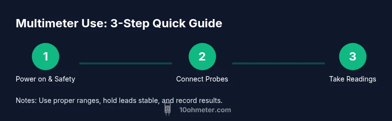
Steps
Estimated time: 15-30 minutes
- 1
Power on and inspect the meter
Turn on the meter, verify the display settles, and check that the fuses are intact. Inspect leads for cracks and test for smooth operation. Confirm you know which jack to use for the range you expect to measure.
Tip: If the display is dim or the fuse blows, stop and inspect for a short or damaged tool. - 2
Connect the probes correctly
Plug the red probe into the voltage/current/ohm jack appropriate for your measurement, and the black probe into the common (COM) jack. Ensure probes are fully inserted and won't slip during measurement.
Tip: Keep hands behind the probes and avoid touching metal tips during measurement. - 3
Select the correct measurement mode and range
Set the meter to DCV, ACV, resistance, or current as required. If unsure, start with auto-range or the highest practical range to avoid overloading the meter.
Tip: Auto-range simplifies use for beginners; manual range can improve accuracy in known conditions. - 4
Make the measurement safely
For voltage, connect across the two points. For current, insert the meter in series with the load after opening the circuit. For resistance or continuity, ensure power is removed and components fully discharged.
Tip: Never measure resistance on a live circuit; always discharge capacitors first. - 5
Interpret readings and verify
Compare readings to expected values from schematics or references. If readings seem off, re-test, check connections, and consider alternative measurement points.
Tip: Record results and note any environmental factors that may affect readings. - 6
Power down and store
Turn off the meter, remove probes from active circuits, and store the device in its case with leads neatly coiled.
Tip: Inspect leads for wear after testing and replace damaged components promptly.
Your Questions Answered
What is a multimeter used for?
A multimeter measures electrical properties such as voltage, current, resistance, and continuity. It helps you diagnose circuits and verify components without destructive testing.
A multimeter measures voltage, current, resistance, and continuity, helping you diagnose circuits safely.
Can I measure current without breaking the circuit?
Current must be measured in series by inserting the meter into the circuit. Do not connect the meter in parallel, as that would short the circuit.
To measure current, insert the meter in series with the load; never place it in parallel.
Is it safe to measure high voltages with a basic meter?
Only if the meter is rated for the voltage and you follow all safety guidelines. Use equipment with proper CAT ratings and personal protective equipment.
Only use rated meters for high voltages and follow safety guidelines.
What is auto-range vs manual range?
Auto-range automatically selects a suitable scale, simplifying use. Manual range lets you lock in a specific range when you know the expected value.
Auto-range is easier for beginners; manual range gives you control when you know the target value.
Why does my meter beep during a continuity test but show open on a suspected path?
Beep indicates low resistance; if there is no beep, the path is not complete, or there may be a poor connection. Recheck connections and test again.
Beep means a closed circuit; if it doesn’t beep, recheck the wiring and test points.
How often should I replace fuses in a multimeter?
Replace fuses whenever blown; inspect for overcurrent damage and ensure replacements match the meter’s specified ratings.
Replace blown fuses and check ratings; don’t use improvised fuses.
Watch Video
Key Takeaways
- Know meter basics before testing
- Always power off when measuring resistance
- Use the correct range and leads
- Interpret results with circuit context