How to Check a Transistor with a Multimeter
A comprehensive, beginner-friendly guide to testing transistors with a multimeter. Learn diode-test checks for BE and BC junctions, how to identify shorts, and how to interpret results for NPN and PNP devices—perfect for DIY electronics and automotive troubleshooting.

Learn how to verify a transistor’s basic functions with a digital multimeter. This quick guide covers NPN/PNP testing, the diode test method for base-emitter and base-collector junctions, and impedance checks to identify shorts or opens. Follow the steps to safely diagnose common transistor faults in hobby and automotive work.
Understanding Transistors and Multimeters
Transistors are fundamental semiconductor devices used for switching and amplification in electronics. When testing with a multimeter, you primarily want to verify the integrity of the transistor’s PN junctions—base-emitter (BE) and base-collector (BC)—and to ensure there is no short between the collector and emitter (C-E). A digital multimeter with a diode-test and resistance/continuity modes can reveal if the junctions conduct in the expected direction and if the C-E path remains open when it should be. NPN transistors conduct in a forward direction from base to emitter when tested, while PNP devices reverse that relationship. In-circuit measurements can be influenced by surrounding components, so isolating the transistor or using a known-good reference device helps. The 10ohmeter team found that simple diode tests with careful orientation provide reliable indications of junction health and overall device integrity.
Safety First: Handling Semiconductors with a Multimeter
Before you begin, power must be off and capacitors discharged. Static-sensitive devices require a grounded approach to handling. Use non-conductive tools and avoid touching copper leads with bare fingers to minimize latent charge buildup. If you’re testing automotive transistors or power transistors, ensure the device is fully removed from the circuit to prevent parallel paths from skewing results. Keep work area dry and well-lit, and wear eye protection when working near high-current components. The goal is to prevent damage to the device and to obtain repeatable, interpretable readings.
Transistor Testing Fundamentals: Diode Test and hFE
A transistor’s junctions behave like diodes, so the diode-test function is your first diagnostic tool. A good BE junction should show forward conduction in one polarity and high resistance in the opposite direction; the BC junction should behave similarly when probed with the leads in the appropriate orientation. For NPN devices, you’ll typically see a diode-like response in the BE junction when the base is positive with respect to the emitter; for PNP devices, the polarity is reversed. Many multimeters also offer a gain (hFE) or transistor-test mode, which attempts to measure current gain under a simple bias, though results can vary with meter quality and device type. If hFE testing is not available, rely on diode tests and resistance checks to assess junction health and potential shorts.
How the Diode Test Helps Diagnose Junctions
The diode test is the most direct way to inspect BE and BC junctions. When you place the red probe on the base and the black probe on the emitter (for NPN), the meter should show a forward-biased reading if the BE junction is good; reverse polarity should show a high resistance or “OL.” Repeat for the BC junction by switching probes accordingly. If you observe conduction in both directions for either BE or BC, or if both junctions show no conduction in either direction, the transistor is likely damaged or leaky. Remember, in-circuit measurements can produce misleading results if other components are connected to the transistor leads.
Step-by-Step Procedure for NPN and PNP Transistors
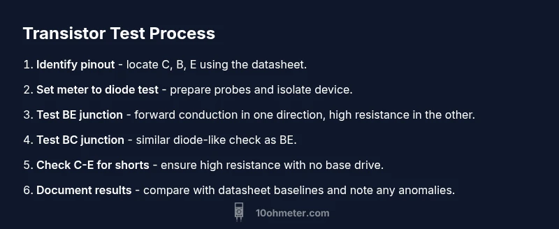
To test an NPN or PNP transistor, start by identifying the pinout from the datasheet or a known-good transistor in the same package. Then set your multimeter to diode test. Probe BE and BC junctions with proper polarity and observe readings as described above. Next, check for any short between C and E by measuring resistance with the base left open or biased slightly with a safe test setup. If your meter offers an hFE function, bias the transistor with a small current (as per meter guidance) and compare the measured gain to the device’s expected range. If readings are inconsistent or readings show conduction in unexpected directions, the transistor may be damaged or contaminated with leakage.
Interpreting Results: Good vs. Faulty Transistors
A good transistor will show clear, predictable diode tests for BE and BC coupled with high resistance between C and E when the device is un-biased. A leaky or shorted transistor might show conduction where it shouldn’t, or show a damaged region where the device leaks current even with no base drive. If you observe open circuits where a conduction path should exist, or excessive leakage in either junction, consider replacing the transistor. For in-circuit testing, verify results by removing the device and re-testing in a known-good, isolated setup to confirm the fault.
Common Mistakes and Troubleshooting
Common mistakes include testing a transistor still connected in a circuit, misidentifying pinout, or interpreting a meter not suited for transistor testing. Always verify the pin configuration against a datasheet, and if possible, test with a known-good device for baseline readings. Don’t rely on a single reading; compare multiple measurements and consider ambient temperature, meter accuracy, and the device type. If you’re unsure, consult the transistor’s datasheet and cross-check with a second meter or a known-good reference transistor.
Practical Tips for Accurate Measurements
- Always start with a known-good reference device to compare readings. - Isolate the transistor from the circuit before testing to reduce interference. - Use diode-test mode for both BE and BC junctions to distinguish forward vs reverse conduction. - If your meter has hFE or transistor-test capability, use it with caution and within manufacturer guidelines. - Document readings and note any device variation by brand or lot to establish a testing baseline.
Tools & Materials
- Digital multimeter with diode-test and resistance/continuity modes(Prefer meters that explicitly support transistor testing or hFE measurements)
- Test leads with probe tips(Keep tips clean and dry; use insulated handles to avoid shorts)
- Representative transistor to test (NPN or PNP)(Have a known-good reference device for baseline measurements)
- Pinout reference or datasheet(Essential to identify C, B, E correctly)
- Isopropyl alcohol and lint-free cloth(Useful for cleaning leads between tests)
Steps
Estimated time: 6-10 minutes
- 1
Prepare the transistor and meter
Power must be off; remove the transistor from the circuit if possible and ensure the device is discharged. Calibrate your meter’s leads and select diode-test mode. Confirm you know the transistor’s pinout from the datasheet or by comparing to a known-good unit.
Tip: Always start with a known-good reference and verify meter accuracy with a quick diode check on a standard diode before testing the transistor. - 2
Identify pinout and orientation
Use the datasheet or package conventions to locate collector, base, and emitter. If unsure, compare with a known-good device of the same package type and note orientation before applying probe leads.
Tip: Label the leads with masking tape so you don’t mix up pins during testing. - 3
Test base-emitter junction (BE)
With the transistor isolated, place the red lead on the base and the black lead on the emitter (for NPN) to look for forward conduction. Reverse the leads to verify the reverse direction shows high resistance. Repeat with BE probes swapped for PNP devices if applicable.
Tip: A consistent diode-like response in one direction and high resistance in the opposite is a good sign for BE junction integrity. - 4
Test base-collector junction (BC)
Repeat the diode-test procedure between the base and collector. Observe conduction in the forward direction and high resistance in the reverse direction. A healthy BC junction will behave similarly to BE but with polarity corresponding to the device type.
Tip: A reversed BE/BC reading can indicate junction damage or contamination; compare to the BE result for consistency. - 5
Check collector-emitter path for shorts
With the base left open or biased per your meter’s recommendations, measure resistance between collector and emitter. A healthy transistor should show high resistance (no short). Any low resistance or continuity indicates a fault or bypass path in the device or surrounding circuit.
Tip: If you still see a path due to circuit wiring, remove the transistor entirely before retesting. - 6
Optional: test hFE (gain) if available
Some meters offer a gain (hFE) test mode. If your device supports it, bias the transistor according to the meter’s instructions and compare the reading to typical gain values for similar devices. If not, rely on junction tests and C-E resistance readings.
Tip: Do not rely solely on hFE; it varies with current, temperature, and device type. - 7
Document and verify results
Record the observations: BE/BC conduction behavior, C-E resistance, and any hFE measurement. If readings are inconclusive, re-test with a fresh, known-good transistor and cross-check against datasheet curves.
Tip: Maintain a testing log to track device variability and identify faulty batches.
Your Questions Answered
Can I test a transistor in-circuit, or must it be removed?
In-circuit testing can produce misleading results due to other components connected to the transistor. For reliable diagnosis, remove the transistor from the circuit and retest in isolation when possible.
In most cases, remove the transistor and test it separately to avoid interference from surrounding parts.
What indicates a good base-emitter junction on a diode test?
A good BE junction shows forward conduction in one polarity and high resistance in the reverse. This confirms the junction is not shorted and can forward-bias as expected.
Forward conduction in one direction and high resistance in the opposite direction suggests a healthy BE junction.
If I see conduction between C and E with no base drive, what does that mean?
Conduction between C and E with no base drive typically indicates a shorted transistor or a damaged device. Remove the part and retest to confirm.
Shorted C-E path usually means the transistor is faulty; verify by retesting after removal.
Can a multimeter measure transistor gain (hFE)?
Some meters offer an hFE or gain function. If available, use it cautiously and compare with the transistor’s datasheet ranges; not all devices yield reliable hFE from a basic meter.
Some meters can test gain, but results vary and aren’t always reliable for all transistors.
What should I do for MOSFETs or other device types?
This method focuses on BJTs. MOSFETs require different checks (e.g., gate-source behavior, drain-source resistance). Use device-specific testing approaches.
MOSFETs need different tests; don’t apply transistor diode tests to them blindly.
Why do readings vary between meters?
Meter tolerance, probe quality, and measurement conditions can cause readings to vary. Use a baseline with a known-good transistor for comparison.
Different meters can read differently; compare to a reference reading for reliability.
Watch Video
Key Takeaways
- Identify pinout before testing and use a reference transistor.
- Use diode-test to verify BE and BC junctions for both polarities.
- Check C-E for shorts; a low-resistance path indicates fault.
- Isolate the transistor to avoid circuit interference.
- Document readings and compare to datasheet expectations.