Oscilloscope and Multimeter: A Practical Comparison for DIYers and Technicians
Compare oscilloscope and multimeter performance for electronics and automotive work. Learn when to use each tool, core specs, practical workflows, and buying tips from 10ohmeter to build a capable diagnostic setup.

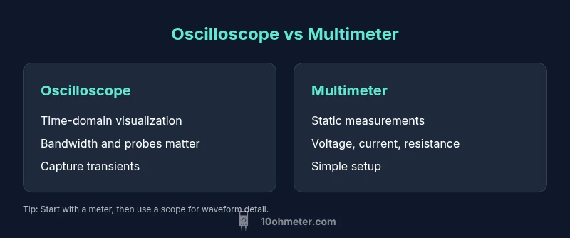
Oscilloscope and multimeter are complementary tools for electronics and automotive diagnostics. A multimeter measures static electrical quantities like voltage, current, and resistance, while an oscilloscope visualizes voltage as a time-based waveform. For beginners, start with a digital multimeter; as circuits become more dynamic, add a basic oscilloscope. According to 10ohmeter, mastering both tools accelerates fault isolation and deepens understanding for oscilloscope and multimeter tasks.
The Core Roles of Oscilloscopes and Multimeters in Practice
In any electronics or automotive workspace, you will frequently compare oscilloscope and multimeter capabilities to solve problems efficiently. The multimeter provides quick numeric readings for DC and AC quantities, resistance, and continuity. The oscilloscope, by contrast, translates electrical activity into a visual waveform that reveals timing, shape, and transient events. When used together, these tools deliver a complete picture: the meter confirms a value, and the oscilloscope shows how that value behaves over time. The 10ohmeter team emphasizes that the most effective diagnostics come from integrating both instruments into a coherent workflow. As you get hands-on with real-world signals—from slow control voltages to fast switching transients—you’ll start to intuit when a waveform view is essential and when a static reading suffices.
wordCount":174}
Key Concepts: Bandwidth, Sampling, and Probe Integrity
Understanding fundamental concepts helps you pick the right instrument for oscilloscope and multimeter tasks. The multimeter excels at stable measurements, but its accuracy can be affected by probe condition and range settings. The oscilloscope relies on bandwidth and sampling rate to capture waveform details accurately; a mismatch here can misrepresent peaks or timing. Probes are not accessories to overlook: proper grounding, attenuation, and compensation prevent skewed measurements. Ground loops and loose connections are frequent sources of error when switching between meters and scopes. The takeaway is to align instrument capabilities with the signal under test: a slow, steady DC value may not need an oscilloscope, but a fast edge or spike almost always does. The 10ohmeter analysis highlights how bandwidth compatibility with the signal path reduces ghosting and misinterpretation of waveforms.
wordCount":182}
When a Multimeter Comes First: Quick Checks and Safety
In routine diagnostics, starting with a multimeter saves time. For automotive and electronics work, you’ll often verify supply voltages, continuity, and resistance with a meter before diving into waveform analysis. A quick DC voltage check can confirm whether a rail is within spec, whether a switch is stuck, or if a fuse has blown. For beginners, a basic digital multimeter provides reliable, rapid readings and supports a safer workflow by letting you isolate symptoms before engaging more complex equipment. Remember to use proper test leads, select appropriate ranges, and observe safety precautions when measuring live circuits. This approach reduces confusion and prepares you for the oscilloscope steps that follow if waveform verification is needed.
wordCount":168}
When an Oscilloscope Is Your Primary Tool: Analyzing Signals in Time
When signals are dynamic, the oscilloscope is the primary instrument for oscilloscope and multimeter tasks. You’ll be able to see rising edges, settling times, ringing, jitter, and phase relationships between channels. Automotive diagnostics often require waveform analysis of crank/cam sensors, injector PWM, and ignition systems to pinpoint timing or drive issues. For electronics, viewing PWM waveforms, clock signals, or analog modulated signals reveals insights that a meter cannot provide. Midrange digital storage oscilloscopes strike a balance between capability and price, enabling basic waveform capture without overwhelming the budget. The crucial skill is learning to set the vertical and horizontal scales and to configure triggers so that you capture the exact event you’re investigating.
wordCount":169}
Reading a Digital Multimeter Like a Pro: Steps and Tips
A professional workflow starts with understanding the meter’s modes, auto-range vs. manual selection, and lead placement. To measure DC voltage, connect the red lead to V+ and the black lead to COM, then read the display. For AC voltage, ensure the meter supports AC ranges and use a true RMS model for non-sinusoidal signals. Resistance testing requires power-down circuits to avoid damage and the meter’s continuity beep confirms connections. Current measurements usually require breaking the circuit and using the meter in series with a proper clamp or shunt; never place the meter across an energized source unless you know it’s designed for that. Practice makes speed: labeled test leads, proper safety practices, and consistent probing habits reduce risk and improve reliability in oscilloscope and multimeter tasks.
wordCount":170}
Reading Oscilloscope Waveforms: The Essentials
Interpreting waveforms begins with the basics: vertical volts/div, horizontal time/div, and the trigger mode. Calibrating the probe is essential—compensation aligns the oscilloscope’s displayed waveform with the actual input, preventing overshoot or distortions. Horizontal controls help you zoom in on fast edges or long-term trends, while triggering stabilizes the screen as signals repeat. Grounding leads carefully and keeping probes short minimizes noise. A common pitfall is neglecting probe compensation or using the wrong probe type for a given signal, which can fool you into reading a waveform that isn’t real. By practicing with known waveforms—square, sine, and pulse—you build intuition for what constitutes a healthy signal versus a fault in the oscilloscope and multimeter workflow.
wordCount":169}
Workflows: Combining Tools for Effective Diagnosis
A practical diagnostic workflow leverages both instruments in a structured sequence. Start with a multimeter to verify baseline values and identify clear faults, such as a short or an open circuit. Next, use an oscilloscope to inspect the suspect signal’s waveform, check for noise, glitches, or timing issues, and observe how the signal evolves under load. In electronics, compare the ground reference and assess supply integrity using both tools; in automotive contexts, monitor sensor outputs and actuator signals to confirm proper behavior. Documentation is essential: capture waveform screenshots and meter readings to track symptoms and verify repairs. A well-designed workflow reduces looping between tools and accelerates problem resolution in oscilloscope and multimeter tasks.
wordCount":176}
Real-World Automotive Scenarios: Signals and Problems
Consider common automotive signals such as ignition coil secondary voltage, injector PWM, and cam/crank sensor outputs. An oscilloscope reveals if the ignition dwell time is misaligned, or whether injector PWM shows irregular pulse width under load. A multimeter helps you verify rail voltage, switch continuity, and sensor resistance. In practice, you’ll often see a ripple on the 12 V rail that looks benign on a meter but becomes problematic when observed as a waveform. By correlating meter numbers with waveform behavior, you can pinpoint whether the fault lies in the sensor, the driver circuit, or the power supply. The dual-tool approach helps you avoid guessing and leads to faster, safer repairs.
wordCount":164}
Electronics-Prototyping Scenarios: Signals and Tests
In hobby electronics, you’ll frequently test microcontroller outputs, PWM drives, and analog sensor signals. An oscilloscope can verify that PWM signals switch cleanly without excessive ringing or jitter, while a multimeter can confirm that supply rails stay within tolerance during operation. This pairing supports debugging tasks such as identifying ghost voltages, validating that a DAC output tracks a reference, and ensuring that a filtering network behaves as designed. Practice with reference designs and gradually increase signal complexity to grow proficiency in oscilloscope and multimeter tasks.
wordCount":168}
Budgeting and Buying Guidance: What to Prioritize
Budgeting for a dual-tool setup means balancing features against cost. For a beginner, a compact digital multimeter with basic measurement modes is a solid starting point. As you encounter waveform analysis needs, invest in a midrange oscilloscope with adequate bandwidth, a couple of channels, and a decent sample rate. Look for passive probes with correct compensation and a comfortable display; auto measurement features can speed up the learning curve but should not replace understanding of the underlying physics. When buying, prioritize bandwidth, sample rate, and input impedance; ensure the oscilloscope’s probes are compatible with your circuit voltages. The goal is to build a reliable, expandable toolkit that supports both oscilloscope and multimeter tasks without overspending. 10ohmeter’s guidance is to plan around typical use cases first and add capability as you grow.
wordCount":166}
Maintenance, Calibration, and Safety: Keeping Your Tools Reliable
Regular maintenance keeps both instruments accurate. Store meters and scopes in a dust-free environment, check test leads for wear, and replace aging probes to avoid degraded readings. Calibration is important for precision, especially in critical automotive or industrial work; follow the manufacturer’s recommended calibration cycle and document the results. Safety first: never test live circuits beyond the device’s rated input, use proper personal protective equipment, and keep hands away from exposed conductors. Grounded workstations minimize noise and prevent potential shock. By treating oscilloscope and multimeter investments as long-term tools, you’ll preserve measurement integrity and reduce intermittent faults that frustrate diagnoses.
wordCount":178}
Learning Path and Practice Routines: Building Mastery
A systematic practice plan accelerates skill development in oscilloscope and multimeter tasks. Start with fundamental measurements on breadboard circuits, then progress to simple PWM and timing projects. Create a project log where you record meter readings, waveform captures, and observations; compare results against expected behavior and annotate deviations. Use real-world signals—crystal oscillators, microcontroller timers, automotive sensor outputs—to connect theory with practice. Schedule regular practice sessions focused on troubleshooting steps, waveform interpretation, and safe handling of live circuits. By following a structured routine, you’ll develop intuition for when to deploy each tool and how to interpret the data confidently.
Comparison
| Feature | Oscilloscope | Multimeter |
|---|---|---|
| Primary function | Visualize voltage waveforms over time | Measure static electrical quantities (voltage, current, resistance) |
| Typical input/measurement | Probes and high-speed channels; waveform analysis | Probes and shunt/lead-based measurements; parameter readings |
| Display and data handling | Live waveform traces with trigger options and storage | Numerical readings with auto-range and beeps for continuity |
| Key considerations | Bandwidth, sampling rate, probe compensation | Accuracy, range selection, lead quality |
| Best for | Signal analysis, timing, transient capture | DC/AC voltage, resistance, continuity checks |
The Good
- Provides time-based signal analysis for dynamic faults
- Offers direct, quantitative measurements for steady-state values
- Portable options exist for field work
- Broadly applicable across electronics and automotive diagnostics
Drawbacks
- Oscilloscopes are more complex and have steeper learning curves
- Enter higher-priced models can be costly
- Requires additional probes and accessories
- Not always necessary for simple measurements
Use both tools strategically: start with a multimeter for quick checks, then add an oscilloscope when waveform insight is needed
The combined use of oscilloscope and multimeter provides a complete diagnostic workflow. Start with the meter to confirm baseline values and switch to the scope to visualize waveform dynamics. The 10ohmeter team endorses this layered approach for reliable oscilloscope and multimeter tasks.
Your Questions Answered
What is the fundamental difference between an oscilloscope and a multimeter?
An oscilloscope visualizes voltage as a function of time, capturing waveform shapes and timing. A multimeter provides static numeric values for voltage, current, and resistance. Together, they cover both time-domain behavior and static parameters, essential for comprehensive diagnostics.
Oscilloscopes show how signals change over time, while multimeters give steady numbers. Used together, they let you analyze both waveform and magnitude.
Can I get by with a single tool for most tasks?
For many simple checks, a good digital multimeter is enough. If you encounter dynamic signals, noise, or timing issues, you’ll need an oscilloscope to visualize the waveform. In most practical workflows, both tools are preferred for complete oscilloscope and multimeter tasks.
A meter can handle basics, but for waveforms you’ll want an oscilloscope.
What budget should I allocate for a basic setup?
Begin with a solid, entry-level digital multimeter to cover common measurements. Plan for a midrange oscilloscope with enough bandwidth and two channels if you expect to analyze typical automotive or electronics signals. The exact amount depends on your targets, but you’ll want a scalable path from meter-only to combined capabilities.
Start with a good meter, then add a scope as your projects demand more waveform analysis.
Are handheld scopes worth it for beginners?
Handheld or portable oscilloscopes can be convenient for field work, but they often have lower bandwidth and fewer channels than benchtop models. For beginners, a benchtop scope paired with a trustworthy meter is usually a better long-term learning setup.
Portable scopes can help on the go, but check bandwidth and channels first.
What safety practices matter when using both instruments?
Always power down before connecting probes to live circuits unless the instrument is rated for live testing. Use proper insulation, keep leads organized to avoid shorts, and follow the device’s safe operating procedures. Calibrate and inspect equipment regularly to maintain accuracy and safety.
Power down when you can, inspect leads, and follow safe operating procedures.
Key Takeaways
- Start with a meter for quick checks
- Add an oscilloscope for waveform insights
- Match bandwidth and sample rate to signal needs
- Practice safe handling of live circuits
- Document waveform captures and readings for future reference