Measuring Frequency with a Multimeter: A Practical Guide
Learn how to measure frequency with a multimeter that supports Hz mode. This step-by-step guide covers compatibility, safe test setups, interpretation, accuracy considerations, and practical tips for electronics and automotive tasks.

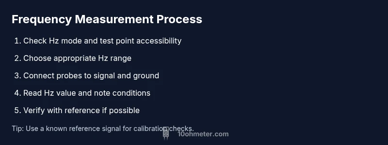
By using a frequency-capable multimeter, you can measure the electrical signal's rate in hertz directly at a test point. Ensure your meter supports Hz measurement and choose the frequency/Hz setting, or the equivalent AC frequency mode. Connect probes to the signal under test, stay within the meter’s input limits, and read the value on the display. Note that accuracy varies by model.
What the phrase "multimeter can measure frequency" means in practice
A multimeter that can measure frequency exposes a dedicated Hz (or AC Hz) function. When you select this mode, the meter interprets the incoming waveform and displays its repetition rate in hertz. This capability is particularly useful for quick checks in hobby electronics and automotive diagnostics, where signals like PWM, servo pulses, or carrier frequencies appear. The practical takeaway is that not all meters include this feature, so verifying Hz mode support is essential before planning measurements. According to 10ohmeter, frequency readings from a compatible meter provide a fast, non-visual reference for signal rate during bench work or field testing.
Compatibility matters: which models actually measure frequency?
Not every multimeter has a frequency function. Entry-level units typically focus on voltage, current, and resistance, while more advanced models add frequency measurement. To know if your meter can measure frequency, consult the user guide for a Hz or frequency option, check the front panel for a Hz symbol, or explore the meter’s measurement modes in the menu. The presence of a frequency function means you can obtain a direct Hz readout rather than inferring from other parameters. This is convenient for quick diagnostics and for validating timing characteristics in simple circuits.
How to locate and switch to Hz mode on common meters
Locating Hz mode involves scanning the dial or menu for a symbol such as Hz or f. If your meter uses a rotary switch, turn to the Hz setting and confirm that the display shows a frequency symbol when a signal is present. In some models, Hz mode is tucked under a secondary function or requires pressing a shift or mode button. If your display shows a DC-only reading, you may be in the wrong mode. Always consult the manual to confirm the exact sequence for entering Hz mode on your specific device.
Safe setup and probe technique for frequency reading
Accessing the signal point safely is critical. Use proper probes or leads and avoid direct contact with exposed conductors. For high-frequency signals, keep test leads short and minimize loop area to reduce noise. Ground references should be stable to prevent ground bounce from skewing readings. If you’re measuring at a powered point, use isolation or non-contact methods where possible and never bypass safety features just to obtain a reading.
How to perform a frequency reading: a practical workflow
Begin with a clear test point that represents the signal you want to measure. If possible, start with a known reference signal to validate the setup. Then power up the circuit and enable Hz mode on the meter. Attach probes to the test point and ground as appropriate, watch the display for a stable frequency value, and record multiple readings to confirm consistency. If the signal is unstable, use averaging if your meter supports it and note any jitter.
Interpreting results and recognizing limitations
A Hz reading indicates how many times per second the waveform repeats. Remember that many hobby signals are not perfect sine waves, and meters may respond differently to square waves, PWM, or bursts. Frequency readings can be affected by probe capacitance, wiring, and the source's impedance. If readings fluctuate, try stabilizing the test point, shortening leads, or using a reference source for comparison. When precise timing matters, corroborate with another instrument such as an oscilloscope or frequency counter.
Accuracy considerations: what affects your reading (without overclaiming)
Accuracy depends on the meter’s clock, sampling method, and input stage. Some meters have a broader frequency range but limited precision at higher rates. Others offer better stability but a narrower bandwidth. Temperature, noise, and probe quality can also influence results. For best results, measure in a controlled setup, compare readings under the same conditions, and avoid relying on a single data point for critical decisions.
When a multimeter is sufficient vs. when to reach for a scope
For quick checks and rough timing estimates, a frequency-capable multimeter is convenient. If your task requires waveform shape, jitter analysis, or precise timing relationships, an oscilloscope or dedicated frequency counter offers richer insight. Use the multimeter for fast validation, and reserve an oscilloscope for deeper analysis of non-sinusoidal signals or complex timing scenarios.
Real-world examples: electronics and automotive contexts
In electronics, you might measure the carrier frequency of a radio module or the PWM frequency controlling a motor driver. In automotive work, a multimeter can help gauge injector drive signals or sensor output frequencies that are within the meter’s Hz range. Each scenario benefits from a stable test setup and consistent measurement technique to ensure readings are meaningful and reproducible.
Maintenance, verification, and best practices
Regularly check that your meter’s Hz function remains calibrated against a known reference. When possible, validate readings with another instrument, especially for critical tasks. Keep probes clean, use proper accessories, and store equipment away from moisture or extreme temperatures. Document the measurement setup and conditions to support repeatability in future tests.
Wrapping up: a concise guide to frequency measurement with a multimeter
The key is to verify Hz capability, set the correct mode, connect probes correctly, and interpret the readout in the context of the signal type. With careful practice, a multimeter can be a reliable first tool for frequency assessment in a wide range of electronics and automotive applications.
Tools & Materials
- Digital multimeter with Hz/AC Hz measurement(Must explicitly support frequency measurement (Hz or f) mode; check user manual for exact steps.)
- Test leads and probes(Prefer short, shielded leads to minimize impedance and noise at higher frequencies.)
- Known reference signal source (optional)(Useful to verify meter accuracy during setup and calibration checks.)
- Non-conductive bench mat or work surface(Helps prevent accidental shorts and provides a stable measurement area.)
- Oscilloscope or frequency counter (optional)(Use when waveform shape or higher precision is needed.)
Steps
Estimated time: 20-30 minutes
- 1
Verify Hz capability
Consult your meter’s manual to confirm the Hz or frequency function exists. If present, identify the button or dial position that activates Hz mode and ensure the display shows a Hz icon when a signal is connected.
Tip: If Hz mode is hidden behind a submenu, map out the path on your device to avoid hunting during measurements. - 2
Select the correct Hz range
If your meter offers multiple Hz ranges, select a range that matches the expected signal frequency. Use auto-range if available to let the meter choose the best scale while watching the display for a stable value.
Tip: Avoid forcing the meter into an inappropriate range, which can cause overflow or unstable readings. - 3
Attach probes to the test point
Connect the probe tip to the signal point and the common/shield to ground as appropriate. Keep leads short and avoid adding extra length that can introduce noise.
Tip: Keep the measurement point as close to the source as possible to minimize cable inductance effects. - 4
Prepare the signal source
If possible, use a stable reference or known frequency source for initial verification. Ensure the target circuit is powered only if the meter supports live measurements on that node.
Tip: If the signal is noisy, consider gentle filtering to reduce jitter that can affect the reading. - 5
Read and record the frequency
Observe the Hz reading on the display. Take multiple readings to check consistency and note any fluctuations or jitter. If your meter supports averaging, enable it to stabilize the result.
Tip: Record the environmental conditions (temperature, load) to contextualize the reading. - 6
Cross-check with a reference
Compare the meter’s reading against a known reference or, if available, another instrument like a scope or counter to validate accuracy.
Tip: Any discrepancy should prompt re-check of connections, range, and signal integrity before trusting the value.
Your Questions Answered
Can all multimeters measure frequency?
No. Only meters with a dedicated Hz or frequency function can display a frequency reading. Check the user manual or model specifications to confirm this capability.
Not all multimeters can measure frequency; check your manual to confirm Hz mode.
What affects accuracy when measuring frequency with a multimeter?
Accuracy depends on the meter’s design, range selection, signal quality, and probe setup. Variations in waveform shape or source impedance can influence readings.
Accuracy depends on the meter and signal quality; waveform shape matters.
Should I calibrate my meter for frequency measurements?
Most consumer meters don’t require frequent calibration for basic frequency readings. If you need precision, verify with a known reference or higher-accuracy instrument.
Calibrate only if you need high precision; use references for validation.
When is an oscilloscope better than a multimeter for frequency tasks?
Use an oscilloscope when you need waveform shape, jitter, or timing relationships. A multimeter is great for quick frequency checks, but it can miss waveform details.
An oscilloscope reveals waveform shape and timing; meters are for quick checks.
What safety steps should I take when measuring frequency in automotive work?
Ensure the vehicle is in a safe state, use insulated probes, and avoid high-energy sources. Follow vehicle service manuals and isolate the circuit when possible.
Stay safe by insulating probes and following the vehicle’s manual when measuring signals.
Watch Video
Key Takeaways
- Verify Hz capability before measuring frequency.
- Use short probes and proper grounding for reliable readings.
- Compare readings with a reference when possible.
- Use an oscilloscope for waveform analysis when precision matters.